
TH8082
Enhanced SoloLIN Transceiver
TH8082
≠
Datasheet
Page
1
of
24
3901008082
January 2003
Rev 004
Features
Features
Features
Features
Operating voltage V
S
= 6 to 18 V
Very low standby current consumption of typ. 6.5µA in sleep mode
LIN-Bus Transceiver:
o
Slew rate control for good EMC behavior
o
Fully integrated receiver filter
o
BUS input voltage -27V to 40V
o
Integrated termination resistor for LIN slave nodes (30k
)
o
Wake up via LIN bus
o
Baud rate up to 20 kBaud
o
Compatible to LIN Specification 1.3
Compatible to ISO9141 functions
Control output for voltage regulator with low on ≠ resistance for switchable master
termination
High EMI immunity
Bus terminals proof against short-circuits and transients in the automotive environment
High impedance Bus pin in case of loss of ground and undervoltage condition
Thermal overload protection
High signal symmetry for using in RC ≠ based slave nodes up to 2% clock tolerance
±4kV ESD protection at Bus pin
Ordering Information
Part
No.
Temperature
Range
Package
TH8082
K (-40 to 125 ∞C)
DC (SOIC8)
General Description
General Description
General Description
General Description
The TH8082 is a physical layer device for a single wire data link capable of operating in applications where
high data rate is not required and a lower data rate can achieve cost reductions in both the physical media
components and in the microprocessor which use the network. The TH8082 is designed in accordance to the
physical layer definition of the LIN Protocol Specification, Rev. 1.3.The IC furthermore can be used in
ISO9141 systems.
Because of the very low current consumption of the TH8082 in the sleep mode it's suitable for ECU
applications with hard standby current requirements. This mode allows a shutdown of the whole application.
The included wake-up function detects incoming dominant bus messages and enables the voltage regulator.

TH8082
Enhanced SoloLIN Transceiver
TH8082
≠
Datasheet
Page
2
of
24
3901008082
January 2003
Rev 004
Contents
1. Functional Diagram ................................................................................................... 4
2. Electrical Specification.............................................................................................. 5
2.1
Operating Conditions ............................................................................................ 5
2.2
Absolute Maximum Ratings .................................................................................. 5
2.3
Static Characteristics ............................................................................................ 6
2.4
Dynamic Characteristics ....................................................................................... 8
2.5
Timing Diagrams................................................................................................... 9
2.6
Test circuits for Dynamic and Static Characteristics ........................................... 11
3. Functional Description ............................................................................................ 12
3.1
Initialization ......................................................................................................... 12
3.2
Operating Modes ................................................................................................ 12
3.3
Mode control ...................................................................................................... 12
3.4
LIN BUS Transceiver .......................................................................................... 13
3. Operating under Disturbance ................................................................................. 15
3.1
Loss of battery .................................................................................................... 15
3.2
Loss of Ground ................................................................................................... 15
3.3
Short circuit to battery......................................................................................... 15
3.4
Short circuit to ground......................................................................................... 15
3.5
Thermal overload................................................................................................ 15
3.6
Undervoltage Vcc ............................................................................................... 15
4. Application Hints ..................................................................................................... 16
4.1
LIN System Parameter........................................................................................ 16
4.1.1.
Bus loading requirements ............................................................................ 16
4.1.2.
Recommendations for system design.......................................................... 16
4.2
Min/max slope time calculation ........................................................................... 18
4.3
Application Circuitry ............................................................................................ 19
5. Pin Description......................................................................................................... 20
6. Mechanical Specification ........................................................................................ 21
7. ESD/EMC Remarks .................................................................................................. 22
7.1
General Remarks................................................................................................ 22
7.2
ESD-Test ............................................................................................................ 22
7.3
EMC.................................................................................................................... 22
8. Reliability Information ............................................................................................. 23
9. Disclaimer................................................................................................................. 23

TH8082
Enhanced SoloLIN Transceiver
TH8082
≠
Datasheet
Page
3
of
24
3901008082
January 2003
Rev 004
List of Figures
List of Figures
List of Figures
List of Figures
Figure 1 - Block Diagram ......................................................................................................................... 4
Figure 2 - Input / Output timing ................................................................................................................ 9
Figure 3 ≠ Receiver debouncing .............................................................................................................. 9
Figure 4 ≠ Sleep mode and wake up procedure.................................................................................... 10
Figure 5 - Test circuit for dynamic characteristics ................................................................................. 11
Figure 6 - Test circuit for automotive transients..................................................................................... 11
Figure 7 - Receive impulse diagram ...................................................................................................... 13
Figure 8 - Slope time calculation............................................................................................................ 18
Figure 9 - Application Circuitry............................................................................................................... 19
Figure 10 - Pin description SOIC8 package .......................................................................................... 20
TH8082
Enhanced SoloLIN Transceiver
TH8082
≠
Datasheet
Page
5
of
24
3901008082
January 2003
Rev 004
2.
2.
2.
2. Electrical Specification
Electrical Specification
Electrical Specification
Electrical Specification
All voltages are referenced to ground (GND). Positive currents flow into the IC.
The absolute maximum ratings (in accordance with IEC 134) given in the table below are limiting values that
do not lead to a permanent damage of the device but exceeding any of these limits may do so. Long term
exposure to limiting values may effect the reliability of the device.
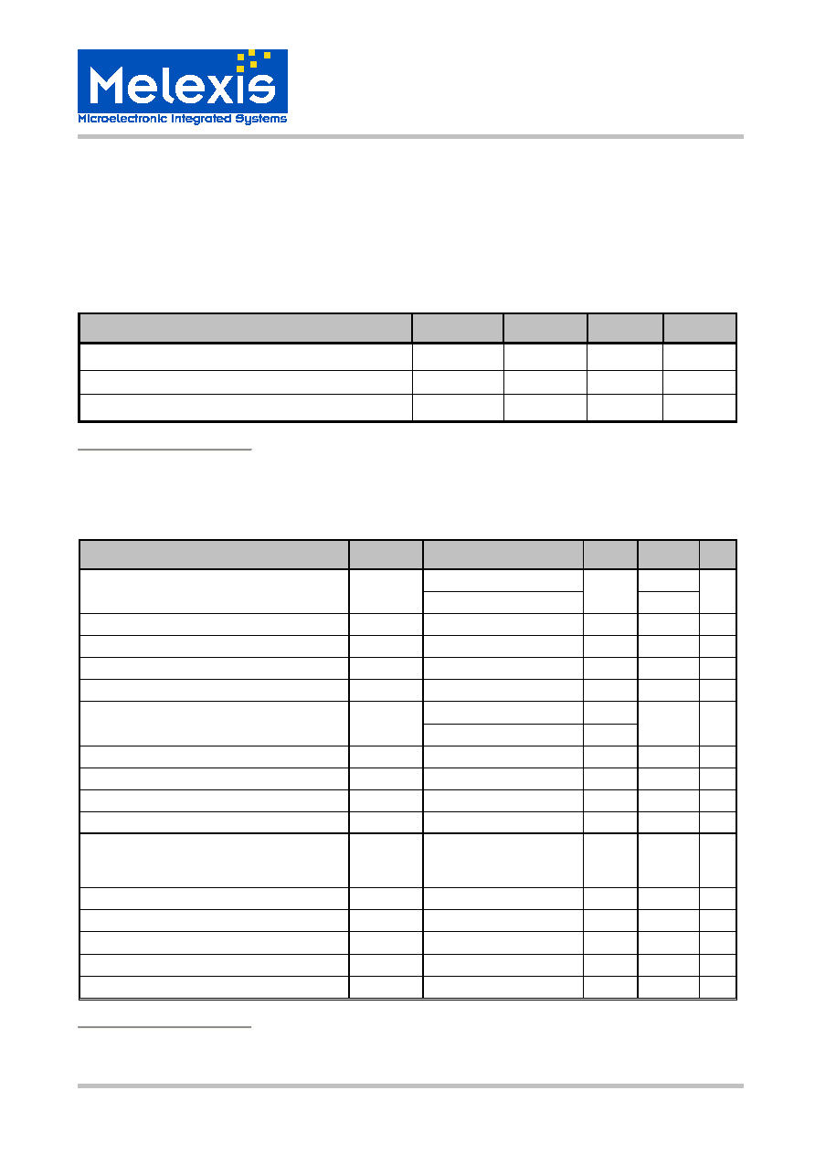
2.1 Operating
Conditions
Parameter
Symbol
Min
Max
Unit
Battery supply voltage
[1]
V
S
6 18
V
Supply voltage
V
CC
4.5 5.5
V
Operating ambient temperature
T
amb
-40
+125
∞C
[1]
Vs is the IC supply voltage including voltage drop of reverse battery protection diode, V
DROP
= 0.4 to 1V,
V
BAT_ECU
voltage range is 7 to 18V
2.2 Absolute Maximum Ratings
Parameter
Symbol
Condition
Min
Max
Unit
t < 1 min
30
Battery Supply Voltage
V
S
Load dump, t < 500ms
-0.3
40
V
Supply Voltage
V
CC
-0.3 +7 V
Transient supply voltage
V
S.tr1
ISO 7637/1 pulse 1
[1]
-150
V
Transient supply voltage
V
S..tr2
ISO 7637/1 pulses 2
[1]
100
V
Transient supply voltage
V
S..tr3
ISO 7637/1 pulses 3A, 3B
-150
150
V
t < 500ms , Vs = 18V
-27
BUS voltage
V
BUS
t < 500ms ,Vs = 0V
-40
40 V
Transient bus voltage
V
BUS..tr1
ISO 7637/1 pulse 1
[2]
-150
V
Transient bus voltage
V
BUS.tr2
ISO 7637/1 pulses 2
[2]
100
V
Transient bus voltage
V
BUS.tr3
ISO 7637/1 pulses 3A, 3B
[2]
-150 150 V
DC voltage on pins TxD, RxD
V
DC
-0.3 7 V
ESD capability of any pin
ESD
HB
Human body model,
equivalent to discharge
100pF with 1.5k
,
-4 4
kV
Maximum latch - up free current at any Pin
I
LATCH
-500 500 mA
Maximum power dissipation
P
tot
At
T
amb
= 125 ∞C
197
mW
Thermal impedance
JA
in free air
152
K/W
Storage temperature
T
stg
-55 +150 ∞C
Junction temperature
T
vj
-40 +150 ∞C
[1]
ISO 7637 test pulses are applied to VS via a reverse polarity diode and >2uF blocking capacitor .
[2]
ISO 7637 test pulses are applied to BUS via a coupling capacitance of 1 nF.
