 | –≠–ª–µ–∫—Ç—Ä–æ–Ω–Ω—ã–π –∫–æ–º–ø–æ–Ω–µ–Ω—Ç: HEDS-973x | –°–∫–∞—á–∞—Ç—å:  PDF PDF  ZIP ZIP |
Features
∑ Small Size
∑ Low Cost
∑ Multiple Mounting Options
∑ Wide Resolution Range
∑ Linear and Rotary Options
Available
∑ No Signal Adjustment
Required
∑ Insensitive to Radial and
Axial Play
∑ - 40
∞
C to +85
∞
C Operating
Temperature
HEDS-973x Series
∑ High Resolution Version of
the HEDS-970x
∑ Two Channel Quadrature
Output
∑ TTL Compatible
∑ Single 5 V Supply
∑ Wave Solderable
Description
The HEDS-973x series is a high
performance, low cost, optical
incremental encoder module.
When operated in conjunction
Small Optical Encoder Modules
Technical Data
ESD WARNING: NORMAL HANDLING PRECAUTIONS SHOULD BE TAKEN TO AVOID STATIC DISCHARGE.
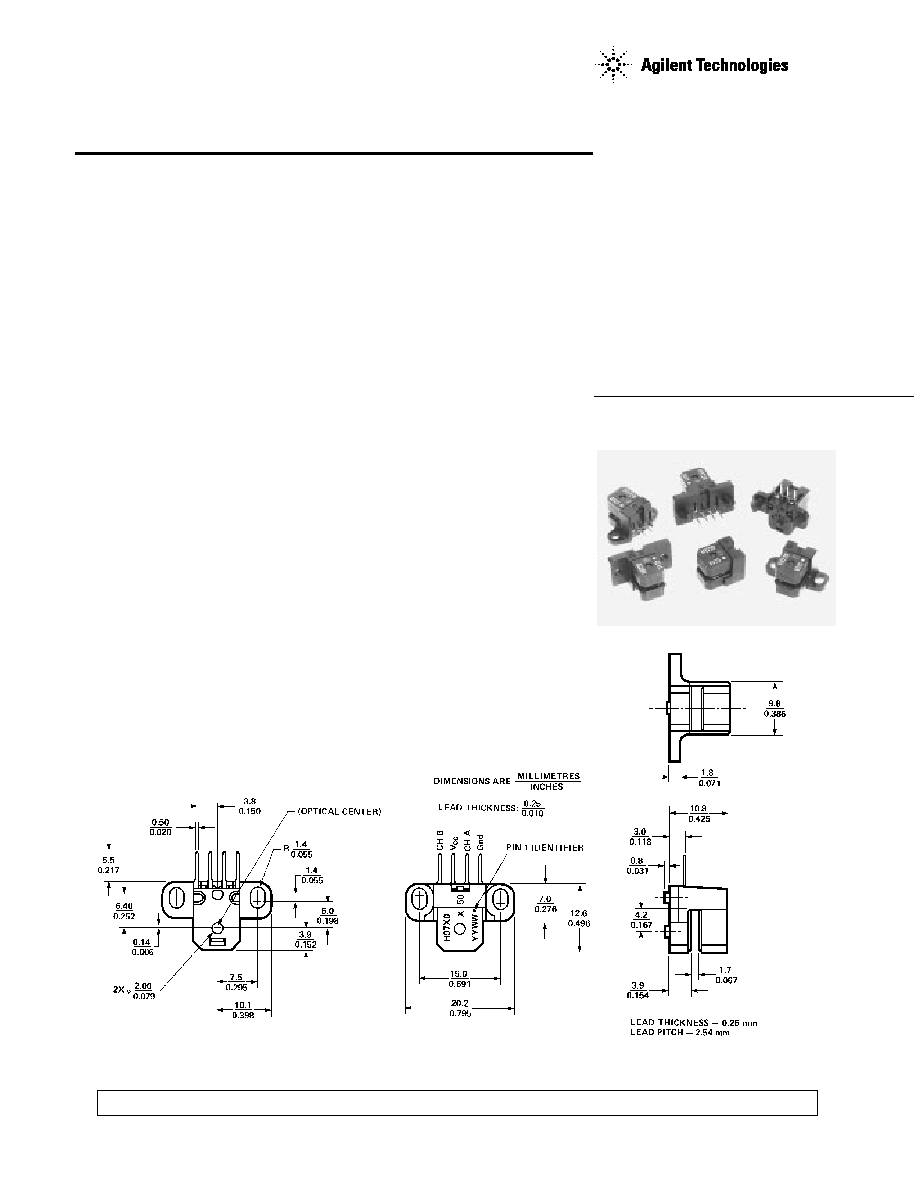
Package Dimensions
Mounting Option #50 - Standard (Baseplane Mounting)
Contact Factory for Detailed Package Dimensions

2
with either a codewheel or
codestrip, this module detects
rotary or linear position. The
module consists of a lensed LED
source and a detector IC enclosed
in a small C-shaped plastic pack-
age. Due to a highly collimated
light source and a unique photo-
detector array, the module is
extremely tolerant to mounting
misalignment.
The two channel digital outputs
and 5 V supply input are accessed
through four solder-plated leads
located on 2.54 mm (0.1 inch)
centers.
The standard HEDS-973x is
designed for use with an 11 mm
optical radius codewheel, or
linear codestrip. Other options
are available. Please contact
factory for more information.
Applications
The HEDS-973x provides
sophisticated motion detection at
a low cost, making closed-loop
control very cost-competitive!
Typical applications include
printers, plotters, copiers, and
office automation equipment.
.
Note: Agilent Technologies
encoders are not recommended
for use in safety critical
applications. Eg. ABS braking
systems, power steering, life
support systems and critical care
medical equipment. Please
contact sales representative if
more clarification is needed.
Theory of Operation
The HEDS-973X is a C-shaped
emitter/detector module. Coupled
with a codewheel, it translates
rotary motion into a two-channel
digital output. Coupled with a
codestrip, it translates linear
motion into a digital output.
As seen in the block diagram, the
module contains a single Light
Emitting Diode (LED) as its light
source. The light is collimated
into a parallel beam by means of
a single lens located directly over
the LED. Opposite the emitter is
the integrated detector circuit.
This IC consists of multiple sets
of photodetectors and the signal
processing circuitry necessary to
produce the digital waveforms.
The codewheel/codestrip moves
between the emitter and detector,
causing the light beam to be inter-
rupted by the pattern of spaces
and bars on the codewheel/code-
strip. The photodiodes which
detect these interruptions are
arranged in a pattern that corre-
sponds to the radius and count
density of the codewheel/code-
strip. These detectors are also
spaced such that a light period on
one pair of detectors corresponds
to a dark period on the adjacent
pair of detectors. The photodiode
outputs are fed through the signal
processing circuitry. Two com-
parators receive these signals and
produce the final outputs for
channels A and B. Due to this
integrated phasing technique, the
digital output of channel A is in
quadrature with channel B (90
degrees out of phase).
Block Diagram

3
Phase (
): The number of electrical
degrees between the center of the
high state of channel A and the
center of the high state of channel
B. This value is nominally 90
∞
e for
quadrature output.
Phase Error (
): The deviation of
the phase from its ideal value of
90
∞
e.
Direction of Rotation: When the
codewheel rotates counterclock-
wise, as viewed looking down on
the module (so the marking is
visible), channel A will lead
channel B. If the codewheel rotates
in the opposite direction, channel
B will lead channel A.
Optical Radius (Rop): The distance
from the codewheel's center of
rotation to the optical center
(O.C.) of the encoder module.
Angular Misalignment Error (E
A
):
angular misalignment of the sensor
in relation to the tangential
direction. This applies for both
rotary and linear motion.
Mounting Position (R
M
): Distance
from Motor Shaft center of rotation
to center of Alignment Tab
receiving hole.
Output Waveforms
Definitions
Count (N) = The number of bar
and window pairs or counts per
revolution (CPR) of the
codewheel, or the number of lines
per inch of the codestrip (LPI).
1 Shaft Rotation = 360
mechanical
degrees
= N cycles
1 cycle (c) = 360 electrical
degrees (
∞
e)
= 1 bar and
window pair
Pulse Width (P): The number of
electrical degrees that an output
is high during one cycle. This
value is nominally 180
∞
e or 1/2
cycle.
Pulse Width Error (
P): The
deviation, in electrical degrees, of
the pulse width from its ideal
value of 180
∞
e.
State Width (S): The number of
electrical degrees between a
transition in the output of channel
A and the neighboring transition
in the output of channel B. There
are 4 states per cycle, each
nominally 90
∞
e.
State Width Error (
S): The
deviation, in electrical degrees, of
each state width from its ideal
value of 90
∞
e.

4
Recommended Operating Conditions
Parameter
Symbol
Min.
Typ.
Max.
Units
Notes
85
Option A & Q
Temperature
T
-40
∞
C
70
All Other Options
Supply Voltage
V
CC
4.5
5.0
5.5
V
Ripple < 100 mV
p-p
Load Capacitance
C
L
100
pF
3.2 k
pull-up
Count Frequency
40
kHz
(Velocity (rpm) x N)/60
Angular Misalignment
E
A
-2.0
0.0
+2.0
deg.
Mounting Position
R
M
R
OP
-0.14
mm (in.)
(R
OP
-0.006)
Note: The module performance is specified at 40 kHz but can operate at higher frequencies.
Absolute Maximum Ratings
Parameter
Symbol
Min.
Max. Units
Notes
Storage Temperature
T
S
-40
85
∞
C
Option A & Q
70
All Other Options
Operating Temperature
T
A
-40
85
∞
C
Option A & Q
70
All Other Options
Supply Voltage
V
CC
-0.5
7
V
Output Voltage
V
O
-0.5
V
CC
V
Output Current per
I
O
-1.0
5
mA
Channel
Soldering Temperature
260
∞
C
t
5 sec.
Electrical Characteristics
Electrical Characteristics over Recommended Operating Range, Typical at 25
∞
C.
Parameter
Symbol
Min.
Typ.
Max.
Units
Notes
17
40
Option A & Q
Supply Current
I
CC
mA
57
85
All Other Options
High Level Output Voltage
V
OH
2.4
V
I
OH
= -200
µ
A
Low Level Output Voltage
V
OL
0.4
V
I
OL
= 3.86 mA
Rise Time
t
r
180
ns
C
L
= 25 pF,
Fall Time
t
f
40
ns
R
L
= 3.3 k
pull-up
c
L
Shaft
0.13 mm (0.005")
See Mounting Considerations
mm
(inch)

5
Encoding Characteristics
Encoding Characteristics over Recommended Operating Condition and recommended mounting tolerances.
These characteristics do not include codewheel/codestrip contribution. The Typical Values are averages over
the full rotation of the codewheel. For operation above 40 kHz, see frequency derating curves.
Parameter
Symbol
Typical
Maximum
Units
Pulse Width Error
P
5
45
∞
e
Logic State Width Error
S
3
45
∞
e
Phase Error
2
15
∞
e
Note: 3.3 k
pull-up resistors used on all encoder module outputs.
Frequency Derating Curves
Typical performance over extended operating range. These curves were derived using a 25 pF load with a
3.3 k pull-up resistor. Greater load capacitances will cause more error than shown in these graphs.
CHANGE IN STATE WIDTH ERROR
(ELECTRICAL DEGREES)
0
200
0
-15
FREQUENCY (KHz)
100
-10
-5
50
150
-40 ∞C
+25 ∞C
+85 ∞C
A
B
CHANGE IN PULSE WIDTH ERROR
(ELECTRICAL DEGREES)
0
200
15
-5
FREQUENCY (KHz)
5
100
0
10
50
150
-40 ∞C
+25 ∞C
+85 ∞C