XECOM
XE2486
Miniature 2400 bps Modem Module
XE2486
8-97
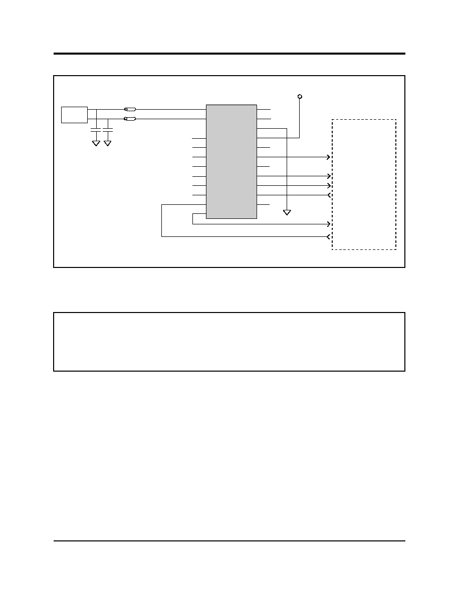
Description
Xecom's XE2486 is a miniature, low cost 2400 bit
per second modem. It provides a complete
modem, including necessary memory and the
DAA in a package just 1.0 inch by 1.25 inches.
User transferable FCC Part 68 registration is
included.
The XE2486 was specifically designed to provide
OEM system designers with a quick, easy and
low-cost way to integrate a 2400 bits per second
modem. Industry standard "AT" commands
provide modem control and configuration. The
XE2486 interfaces with the system host through a
TTL level, serial interface.
Features
∑ Supported Protocols: V.22bis, V.22, V.21, Bell
212A and 103
∑ "AT" commands for modem control and
configuration.
∑ Small Size: 1.25 inches long, 1.0 inches
wide, 0.50 inches high.
∑ NVRAM stores commonly dialed numbers
and custom modem configurations
∑ Single +5V supply
∑ Low power CMOS:
Operating: 200 mW (Typ.)
Sleep mode: 50 mW (Typ.
)
xecom
ROM
Modem
Controller
NVRAM
Analog
Front End
DAA
Tip
Ring
Gnd
VCC
TXD
RXD
\DTR
\DSR
\RI
\CTS
\DCD
Serial I/O
RXA
TXA
\SLEEP
\V-D
\HS
RST
Auxilliary I/O
SPK
Block Diagram

XECOM
(2)
XE2486
A
1.240
1.260
31.50
32.00
B
0.990
1.010
25.15
25.65
C
0.490
0.510
12.45
12.95
D
0.120
0.140
3.05
3.56
E
0.090
0.110
2.29
2.79
F
0.060
0.080
1.52
2.03
G
0.090
0.110
2.29
2.79
H
0.790
0.810
20.07
20.57
XE2486 Mechanical Specifications
Pins = 0.010 by 0.020 inches
INCHES
METRIC(MM)
PIN MIN
MAX
MIN
MAX
A
B
C
F
E
F
G
G
H
D
Denotes Pin 1
PIN
NAME
DESCRIPTION
1
Ring
Ring provides half the two-wire con-
nection to the telephone network,
RJ-11 Pin 4. A 1500 volt barrier
isolates Ring from all other circuits.
This isolation must be preserved
throughout the system. The battery
voltage on Ring may be positive or
negative with respect to Tip.
2
Tip
Tip provides half the two-wire con-
nection to the telephone network,
RJ-11 Pin 3. A 1500 volt barrier
isolates Tip from all other circuits. This isolation must be preserved throughout
the system. The battery voltage on Tip may be positive or negative with respect
to Ring.
3,4
N/A
Not used; Do not connect any circuitry to these Pins.
XE2486
1
22
2
21
20
3
19
4
18
5
17
6
16
7
15
8
14
9
13
10
12
11
RING
TIP
RXA
TXA
SPK
N/C
N/C
/SLP
N/C
TXD
RXD
N/C
RST
GND
VCC
/HS
/DCD
/CTS
/RI
/DSR
/DTR
/V-D
Pin Configuration and Descriptions

XECOM
(3)
XE2486
5
SPK
SPK provides the audio output to a speaker. Speaker output is controlled by the
ATL and ATM commands. The input impedance to the speaker driver must be
greater than 300 ohms.
6, 7
N/C
No Connection
8
/SLP
This active low output indicates when the modem is in the sleep mode.
9
N/C
No Connection
10
TXD
TXD provides serial data input from the host. A logic high represents a "Mark"
and a low represents a "Space".
11
RXD
RXD provides serial data output to the host. A logic high represents a "Mark"
and a low represents a "Space".
12
/V-D
The Voice-Data ouptut can be used to drive an external relay for switching
between the modem and handset connected to the same telephone line.
13
/DTR
Data Terminal Ready is an active low input to the modem. The AT&D command
sets the function of DTR.
14
/DSR
Data Set Ready is an active low output from the modem. Its operation is
determined by the AT&S command.
15
/RI
Ring Indicator is an active low output which marks the presence of a ring on the
line.
16
/CTS
Clear to Send is not used on the XE2486; it will remain low at all times.
17
/DCD
Data Carrier Detect goes low to indicate receipt of a valid incoming carrier. The
AT&C1 command enables the carrier detect function.
18
/HS
This active low output indicates when the XE2486 has made a 2400 bps
connection.
19
VCC
VCC provides the +5 volt power required by the modem.
20
Gnd
Ground provides the common reference for the XE2486.
21
RST
This active high input cause a hardware reset in the XE2486. The reset pulse
must be held high for at least 10 milliseconds to correctly reset the modem.
22
N/C
No Connection
PIN
NAME
DESCRIPTION
Pin Descriptions
continued

XECOM
(5)
XE2486
AT Commands
Modes of Operation
The XE2486"AT" commands provide two
operational modes in the XE2486; Command
Mode and Data Mode.
Data Mode: The XE2486 enters data mode after
it establishes a modem link and issues a
"CONNECT" result code. In Data Mode the
modem transmits all signals on Transmit Data
(TXD) to the remote modem and puts data from
the remote modem onto Received Data (RXD).
When the modem exits data mode, it issues a "NO
CARRIER" result code.
Command Mode: The XE2486 enters command
mode on power-up, reset, a lost connection, or
escape code receipt. In command mode the
modem accepts commands from the host on
transmit data. The modem returns appropriate
responses on received data.
Command Line Format
Command lines issued to the modem follow a
strict format. The ATprefix begins each command.
The command buffer stores the command line
which is executed upon receipt of a carriage
return. Until executed, the command line can be
editied with a backspace.
Command Prefix - Each command begins with
the AT prefix. The "A" and "T" may be both upper
case or both lower case but cannot be of different
cases. The prefix identifies the speed and parity of
the host. The modem measures the width of
incoming bits to determine speed and compares
parity bits of the two characters to determine parity.
Command Line - A command line may include a
series of commands. The modem executes such
commands in the sequence they appear. A
carriage return terminates the command line and
executes the commands. Register S3 allows
selection of another character to terminate the
command line.
Command Buffer - The command buffer holds a
maximum of 40 characters, including the AT
prefix. Space inserted into the command line do
not fill space in the command buffer. Attempting to
load a longer command line causes the modem to
issue an "ERROR" result code and the commands
are not executed.
Command Line Editing - A backspace can be
used to edit the command line beforeexecution.
The backspace erases the previous character in
the command line. Register S5 allows selection of
a character other than a backspace to edit the
command line.
Re-Execute Last Command - An "A/" causes the
modem to re-execute the last command line. This
command which does not require the "AT" prefix.
Ommitted Parameters - Most commands include a
parameter which determines how the functions will
be set. When this parameter is omitted from the
command string, it is assumed to be a 0.
Escape C haracter s - A 3-character escape
sequence switches the modem from data to
command mode while remaining on line. The
escape character, Register S2, must be entered 3
times in succession within a 1 second guard time
to execute the escape. The default escape
sequence is "+++."
Result Codes - The modem issues a result code
after each action. Result codes may be provided
as full words, numeric codes or may be disabled all
together. Each result code ends with a carriage
return when numeric result codes are chosen.
When full word result codes are chosen, a Line
Feed and Carriage Return preceed and follow
each result code.