 | –≠–ª–µ–∫—Ç—Ä–æ–Ω–Ω—ã–π –∫–æ–º–ø–æ–Ω–µ–Ω—Ç: SMTHDTxx | –°–∫–∞—á–∞—Ç—å:  PDF PDF  ZIP ZIP |

Application Specific Discretes
A.S.D.
TM
SMTHDTxx
TRISIL
TM
DISCRETE SOLUTION FOR ISDN PROTECTION
Æ
UNDIRECTIONAL CROWBAR
PROTECTION.
PEAK PULSE CURRENT:
IPP = 75 A , 10/1000
µ
s.
HOLDING CURRENT = 150mA.
BREAKDOWN VOLTAGE:
SMTHDT58 = 58V.
SMTHDT80 = 80V.
SMTHDT120 = 120V.
PACKAGES:
SMTHDTxx = SURFACE MOUNT PACKAGE.
FEATURES
Dedicated protection devices for ISDN LINE
CARD and high speed data telecom lines.
Used with the recommended configuration using
3 components, they will provide =
- Dual bidirectionnal protection, with fixed
breakdown voltage in both common and
differential modes.
- Low capacitancesfrom lines to ground.
- Very good capacitance balance :
C= 30 pF.
DESCRIPTION: TRIBALANCED PROTECTION
April 1999 - Ed: 1A
K
A
FUNCTIONAL DIAGRAM.
Symbol
Parameter
Value
Unit
R
th
(j-l)
Junction-leads Thermal Resistance
SMC
200
∞
C/W
THERMAL RESISTANCES
Symbol
Parameter
Value
Unit
I
PP
Peak pulse current
10/1000
µ
s
8/20
µ
s
75
150
A
I
TSM
Non repetitive surge peak on-state
current
tp = 20 ms
30
A
di/dt
Critical rate of rise of on-state current
Non repetitive
100
A/
µ
s
dv/dt
Critical rate of rise of off-state voltage
67% V
BR
5
KV/
µ
s
T
stg
T
j
Storage and operating junction temperature range
- 40 to + 150
+ 150
∞
C
∞
C
ABSOLUTE RATINGS (limiting values) (-40
∞
C
T
amb
+85
∞
C)
SMC
1/6
Types
I
R
@ V
RM
V
BR @
I
R
V
BO
I
BO
IH
VT
C
max
min
max
min
max
min
max
max
note1
note1
note1
note1
note2
note3
µ
A
V
V
mA
V
mA
mA
mA
V
pF
SMTHDT58
10
56
58
1
80
150
800
150
5
400
SMTHDT80
10
68
80
1
120
150
800
150
5
250
SMTHDT120
10
102
120
1
180
150
800
150
5
200
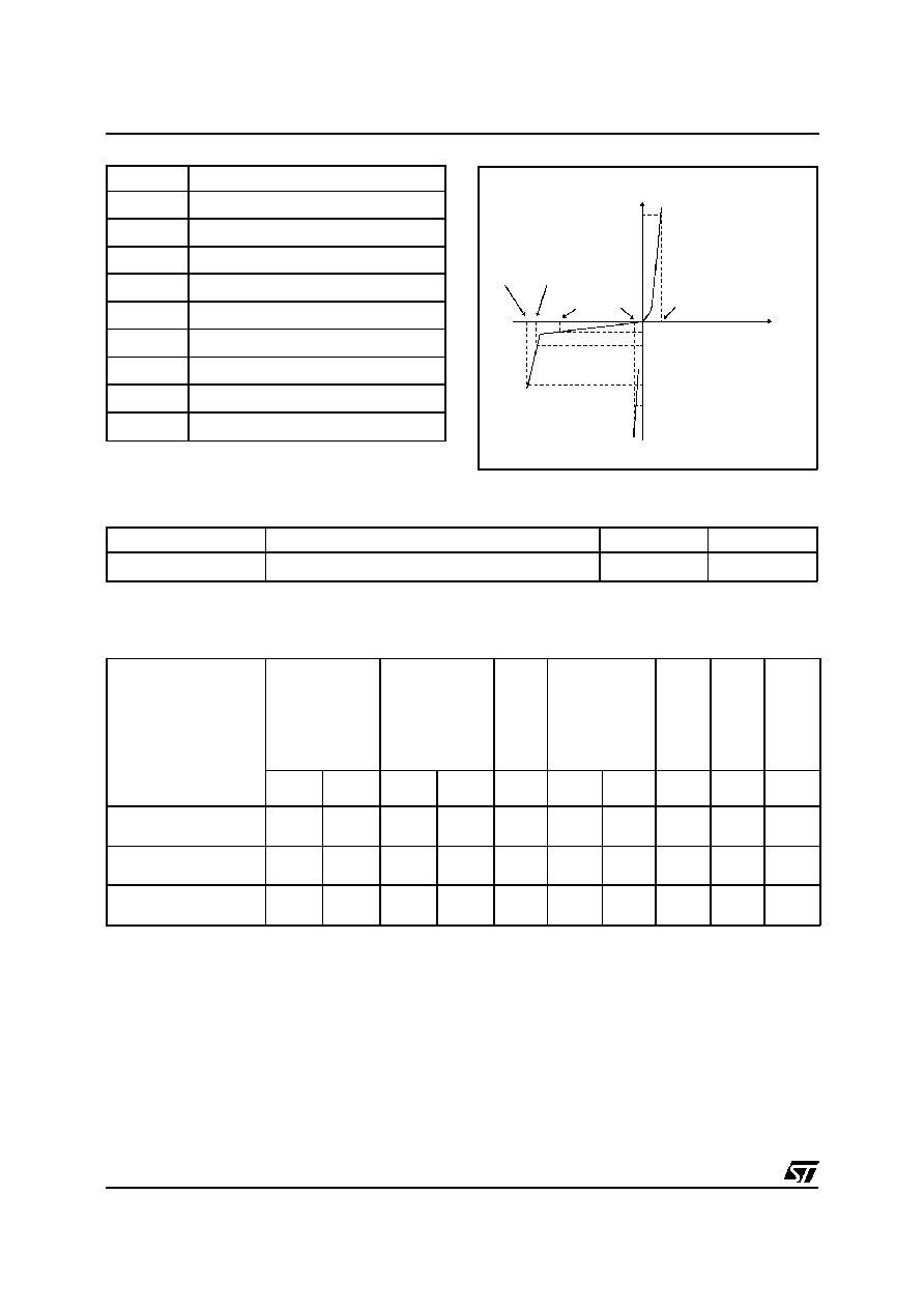
PARAMETERS RELATED TO THE PROTECTION TRISIL.
I
I F
VF
V T
V
VBO VBR
VRM
IH
IBO
I T
I PP
I RM
1mA
V
Symbol
Parameter
V
RM
Stand-off voltage
V
BR
Breakdown voltage
V
BO
Breakover voltage
I
H
Holding current
V
T
On-state voltage
V
F
Forward Voltage Drop
I
BO
Breakover current
I
PP
Peak pulse current
V
F
Forward Voltage Drop
All parameters tested at 25
∞
C, except where indicated.
Note 1 : See the reference test circuit for I
H
, I
BO
and V
BO
parameters.
Note 2 : Square pulse Tp = 500
µ
s - I
T
= 5A.
Note 3 : V
R
= 1V, F = 1MHz.
Parameter
Test conditions
Value
Unit
V
F
I
F
= 5A, T
P
= 500
µ
s
5
V
PARAMETERS RELATED TO THE DIODE.
SMTHDTxx
2/6

REFERENCE TEST CIRCUIT FOR I
H
, I
BO
and V
BO
parameters :
220V
static
relay.
R1
R2
240
140
D.U.T
VBO
measure
I
, I
BO
H
measure
Tp = 20ms
K
Transformer
220V/ 800V
5A
Auto
Transformer
220V/2A
Vout
TEST PROCEDURE :
Pulse Test duration (Tp = 20ms):
- For Bidirectional devices = Switch K is closed
- For Unidirectional devices = Switch K is open.
V
OUT
Selection
- Device with V
BR
150 Volt
- V
OUT
= 250 V
RMS
, R
1
= 140
.
- Device with V
BR
150 Volt
- V
OUT
= 480 V
RMS
, R
2
= 240
.
FUNCTIONAL HOLDING CURRENT (I
H
) TEST CIRCUIT = GO - NOGO TEST.
D.U.T
Switch
Vp =
1KV
20
Surge Generator
10/700
sec
Vp =1KV / Ipp = 25A
F
A
K
50
25
15
220nF
Vbat = 48V
This is a GO-NOGO Test which allows to confirm the holding current (I
H
) level in a functional test
circuit. This test can be performed if the reference test circuit can't be implemented.
TEST PROCEDURE :
1) Adjust the current level at the I
H
value by short circuiting the AK of the D.U.T.
2) Fire the D.U.T with a surge Current : Ipp = 25A , 10/700
µ
s.
3) The D.U.T will come back to the OFF-State within a duration of 50 ms max.
SMTHDTxx
3/6

APPLICATION NOTE
LINE A
LINE B
3.TPUxx
or
3.SMTHDTxx
GND
A
B
LINE A
LINE B
GND
C
CA
B
C
ISDN PROTECTION.
RECOMMENDED CONFIGURATION FOR TRIBALANCED PROTECTION MODE.
Type
CONFIGURATION
C
A
pF
C
B
pF
C
pF
LINE A
LINE B
Max
Max
Max
SMTHDT58
48
0
80
60
30
SMTHDT80
56
0
70
50
30
SMTHDT120
110
0
70
50
30
CAPACITANCE CHARACTERISTICS
TRIPOLE PROTECTION
FULL BALANCED PROTECTION
SMTHDTxx
4/6

U Interface Protection
APPLICATION NOTE
S Interface Protection
Discrete ISDN Protection solution
EQUIVALENT PROTECTION FUNCTION
This topology assumes the same breakdown voltage level in positive and negative for differential or com-
mon mode surge.
A
B
R or PTC
R or PTC
GND
TPUxx
A
B
R or PTC
R or PTC
GN D
TPUxx
TPUxx
A
B
R or PTC
R or PTC
GND
LINE A
LINE B
3 TPUxx
or
3 SMTHDTxx
GND
A
B
TRANSFORMER
SMTHDTxx
5/6