 | –≠–ª–µ–∫—Ç—Ä–æ–Ω–Ω—ã–π –∫–æ–º–ø–æ–Ω–µ–Ω—Ç: L6376 | –°–∫–∞—á–∞—Ç—å:  PDF PDF  ZIP ZIP |

L6376
0.5A HIGH-SIDE DRIVER
QUAD INTELLIGENT POWER SWITCH
0.5 A FOUR INDEPENDENT OUTPUTS
9.5 TO 35 V SUPPLY VOLTAGE RANGE
INTERNAL CURRENT LIMIT
NON-DISSIPATIVE OVER-CURRENT PRO-
TECTION
THERMAL SHUTDOWN
UNDER VOLTAGE LOCKOUT WITH HYS-
TERESYS
DIAGNOSTIC OUTPUT FOR UNDER VOLT-
AGE, OVER TEMPERATURE AND OVER
CURRENT
EXTERNAL ASYNCHRONOUS RESET IN-
PUT
PRESETTABLE DELAY
FOR
OVERCUR-
RENT DIAGNOSTIC
OPEN GROUND PROTECTION
IMMUNITY AGAINST BURST TRANSIENT
(IEC 801-4)
ESD PROTECTION (HUMAN BODY MODEL
±
2KV)
DESCRIPTION
This device is a monolithic quad Intelligent Power
Switch in Multipower BCD Technology, for driving
inductive, capacitive or resistive loads. Diagnostic
for CPU feedback and extensive use of electrical
protections make this device inherently indis-
tructible and suitable for general purpose indus-
trial applications.
November 1996
POWERDIP
16+2+2
MULTIPOWER BCD TECHNOLOGY
CHARGE PUMP
DRIVER
VS
VCP
+
-
+
-
+
-
+
-
VS
OVC
I1
I2
I3
I4
R
DIAG
220nF
22nF
VCP
VS
VC
VP
OVT
UV
ON
OSC
OFF DELAY
ON DELAY
CDON
CDOFF
O4
O3
O2
O1
GND
D94IN076C
1.25V
RS
SHORT CIRCUIT
CONTROL
OFF
OSC
UV
CURRENT
LIMIT
+
-
BLOCK DIAGRAM
ORDERING NUMBERS:L6376 (DIP
L6376PD (PSO)
PowerSO20
1/12

ABSOLUTE MAXIMUM RATINGS (Pin numering referred to PowerSO20 package)
Symbol
Pin
Parameter
Value
Unit
V
s
6
Supply Voltage (t
w
< 10ms)
50
V
Supply Voltage (DC)
40
V
V
s
- V
out
Difference between supply voltage and output voltage
internally limited
V
id
16, 17
Externally Forced Voltage
-0.3 to 7
V
I
id
Externally Forced Current
±
1
mA
I
i
12, 13,
14, 15,
18
Channel Input Current (forced)
±
2
mA
V
i
Channel Input Voltage
-0.3 to 40
V
I
out
2, 3,
8, 9
Output Current (see also I
sc
)
internally limited
V
out
Output Voltage
internally limited
E
il
Energy Inductive Load (T
j
=125
∞
C); Each Channel
200
mJ
P
tot
Power Dissipation
internally limited
V
diag
19
External voltage
-0.3 to V
s
+0.7
V
I
diag
Externally forced current
-10 to 10
mA
T
op
Ambient temperature, operating range
-25 to 85
∞
C
T
j
Junction temperature, operating range (see
Overtemperature Protection)
-25 to 125
∞
C
T
stg
Storage temperature
-55 to 150
∞
C
PIN CONNECTIONS (Top view)
VS
VCP
O2
O1
GND
I1
GND
I2
I3
1
3
2
4
5
6
7
8
9
OFF DELAY
R
DIAG
GND
GND
O4
O3
VP
VC
20
19
18
17
16
14
15
13
12
D93IN030B
I4
10
ON DELAY
11
POWERDIP
GND
O1
I1
O3
VP
V
S
VC
VCP
O2
O4
GND
10
8
9
7
6
5
4
3
2
13
14
15
16
17
19
18
20
12
1
11
GND
D95IN217
I2
I3
ON DELAY
I4
OFF DELAY
R
DIAG
GND
PowerSO20
L6376
2/12
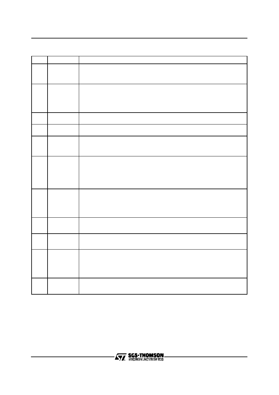
PIN DESCRIPTION (Pin numering referred to PowerSO20 package).
No
Pins
Function
6
V
S
Positive supply voltage.
An internal circuit, monitoring the supply voltage, maintains the IC in off-state until V
S
reaches 9V or when V
S
falls under 8.5V.
The diagnostic is availlable since V
S
= 5V.
7
V
CP
Switch driver supply.
To minimize the output drop voltage, a supply of about 10V higher than V
S
is required. In
order to use the built-in charge pump, connect a filter capacitor from pin1 to pin.
The suggested value assures a fast transition and a low supply ripple even in worse
condition. Using the four channels contemporarily, values less than 68nF have to be
avoided.
2, 3,
8, 9
O
1
, O
2
, O
3
, O
4
High side outputs.
Four independently controlled outputs with built-in current limitation.
1, 10,
11, 20
GND
Ground and power dissipating pins.
These pins are connected to the bulk ground of the IC, so are useful for heat dissipation.
12,13,
14, 15
I
1
, I
2
, I
3
, I
4
Control inputs.
Four independent control signals. The output is held off until the voltage at the
corresponding input pin reaches 1.35V and is turned off when the voltage at the pin goes
below 1.15V.
16
ON DELAY
Programmable ON duration in short circuit.
If an output is short circuited to ground or carryng a current exceeding the limit, the output
is turned-off and the diagnostic activation are delayed. This procedure allows the driving
of hard surge current loads.
The delay is programmed connecting a capacitor (50pF to 15nF) versus ground with the
internal time constant of 1.28
µ
s/pF. The function can be disabled short circuiting this pin
to ground.
17
OFF DELAY
Programmable OFF duration in short circuit.
After the short circuit or overcurrent detection, the switch is held off before the next
attempt to switch on again.
The delay is programmed connecting a capacitor (50pF to 15nF) versus ground with the
internal time constant of 1.28
µ
s/pF.
Short circuiting this pin to ground the OFF delay is 64 times the ON delay.
18
R
Asyncronous reset input.
This active low input (with hysteresis), switch off all the outputs independently from the
input signal. By default it is biased low.
19
DIAG
Diagnostic output.
This open drain output reports the IC working condition. The bad condition (as
undervoltage, overcurrent, overtemperature) turns the output low.
5
V
C
Pump oscillator voltage.
At this pin is available the built-in circuitry to supply the switch driver at about 10V higher
than V
S
. To use this feature, connect a capacitor across pin 4 and pin 5.
The suggested value assures a fast transition and a minimum output drop voltage even in
worse condition. Using the four channels contemporarily, values less than 6.8nF have to
be avoided.
4
V
P
Bootstrapped voltage.
At this pin is available the 11V oscillation for the charge pump, at a typical frequency of
200kHz.
L6376
3/12

ELECTRICAL CHARACTERISTICS (V
s
= 24V; T
j
= -25 to 125
∞
C; unless otherwise specified.)
DC OPERATION (Pin numering referred to PowerSO20 package).
Symbol
Pin
Parameter
Test Condition
Min.
Typ.
Max.
Unit
V
s
6
Supply Voltage
9.5
24
35
V
V
sth
UV UpperThreshold
8.5
9
9.5
V
V
shys
UV Hysteresis
200
500
800
mV
I
qsc
Quiescent Current
Outputs ON, No load
3
5
mA
V
il
12,13,
14,15,
18
Input Low Level
0
0.8
V
V
ih
Input High Level
2
40
V
I
bias
Input Bias Current
V
i
= 0V
-5
-1
0
µ
A
V
i
= 40V
0
5
20
µ
A
V
ihys
Input Comparators Hysteresis
100
200
400
mV
lim
OVT Upper Threshold
150
∞
C
H
Threshold Hysteresis
20
30
∞
C
I
sc
2, 3,
8, 9
Short Circuit Current
V
s
=9.5 to 35V; R
l
=2
0.65
0.9
1.2
A
Output Voltage Drop
I
out
=500mA
;
T
j
=25
∞
C
320
500
mV
I
out
=500mA
;
T
j
=125
∞
C
460
640
mV
I
olk
Output Leakage Current
V
o
=0V; V
i
<0.8V
100
µ
A
V
cl
Internal Voltage Clamp
(V
s
-V
o
each Output)
I
o
=100mA
single pulsed T
p
=300
µ
s
47
52
57
V
V
ol
Low State Output Voltage
V
i
= V
il
; R
L
=
0.8
1.5
V
I
dlkg
19
Diagnostic Output Leakage
Diagnostic Off
25
µ
A
V
diag
Diagnostic Output Voltage
Drop
I
diag
= 5mA
1.5
V
I
dch
16, 17
Delay Capacitors Charge
Current
40
µ
A
L6376
4/12

AC OPERATION (Pin numering referred to PowerSO20 package).
Symbol
Pin
Parameter
Test Condition
Min.
Typ.
Max.
Unit
t
r
-t
f
2, 3, 8, 9
Rise or Fall Time
V
s
= 24V; R
l
= 47
R
l
to ground
3.8
µ
s
t
d
12 vs 9
13 vs 8
14 vs3
15 vs2
Delay Time
1
µ
s
dV/dt
2, 3,
8, 9
Slew Rate (Rise and Fall
Edge)
V
s
= 24V; R
l
= 47
RISE
R
l
to ground
FALL
3
4
5
7.6
7
10
V/
µ
s
t
ON
16
On Time during Short
Circuit Condition
50 pF < C
DON
< 15nF
1.28
µ
s/pF
t
OFF
17
Off Time during Short
Circuit Condition
pin 13 grounded
64
t
ON
50pF < C
DOFF
< 15nF
1.28
µ
s/pF
f
max
Maximum Operating
Frequency
25
kHz
SOURCE DRAIN NDMOS DIODE
Symbol
Parameter
Test Condition
Min.
Typ.
Max.
Unit
V
fsd
Forward On Voltage
I
fsd
= 500mA
1
1.5
V
I
fp
Forward Peak Current
t
p
= 10ms; duty cycle = 20%
1.5
A
t
rr
Reverse Recovery Time
I
fsd
= 500mA; dI
fsd
/dt = 25A/
µ
s
200
ns
t
fr
Forward Recovery Time
50
ns
50%
50%
td
td
t
90%
90%
10%
10%
tf
tr
t
Vin
Vout
D94IN127A
50%
50%
SWITCHING WAVEFORMS
Vs
D94IN126A
Vsth
Vshys
UNDERVOLTAGE COMPARATOR HYSTERESIS
L6376
5/12