BP1045A 622.08 MHz SAW Filter
RF Monolithics, Inc.
Phone: +1(972)233-2903
European Sales Office
4347 Sigma Road Fax: +1(972)387-8148
Dallas, Texas 75244 e-mail:
info@rfm.com
USA Home page:
www.rfm.com
BP1045A 7/22/1999 R
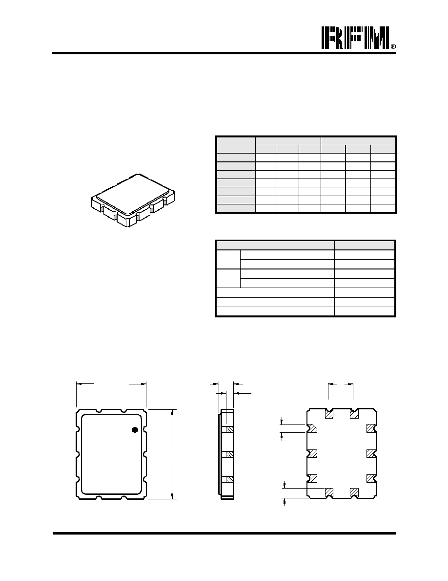
Electrical Connections
Connection
Terminals
Port 1 Hot 10
Port 1 Gnd Return 1
Port 2 Hot 5
Port 2 Gnd Return 6
Case Ground All Others
Absolute Maximum Ratings
Rating
Value
Units
Maximum Incident Power in Passband +10 dBm
Max. DC voltage between any 2 terminals 30 VDC
Storage Temperature Range -40 to +85
�
C
Max Soldering Profile 265
�
C for 10 s
�
Designed for SONET and SDH Clock Recovery
�
Low Insertion Loss
�
9.1 x 7.1 mm Surface-Mount Case
�
50
Input and Output
See Associated Plots
Characteristic
Sym
Min
Typ
Max
Units
Notes
fc 622.080
Center Frequency Nominal
Center Frequency Limits 621.93 622.23
MHz 1
IL 13.0 15.5 17.5 1, 2
1.0
dB
1, 2, 5
Q
3dB
700 800 900 -- 1, 2, 4
BW
3
780 kHz 1, 2
-0.33
�
/ kHz 1, 2, 6
Passband Insertion Loss at fc
Amplitude Variation
Loaded Q
3 dB Bandwidth
Transmission Phase Slope over 3 dB Bandwidth
Phase Deviation from Linear over 3 dB Bandwidth 10
�
1, 2, 7
25 30
Rejection First Sidelobes (at approx. fc
�
1.6 MHz)
Ultimate (DC to 800 MHz, excluding main & first sidelobes) 28 40
dB 1, 2, 3
Operating Temperature Range T
A
-40 +85
�
C 1
Impedance Matching None to 50
Source and Load
Case Style SM9171-10 9.1 x 7.1 mm Nominal Footprint
Lid Symbolization (YY = year, WW = week) RFM BP1045A YYWW
Notes:
1. Unless noted otherwise, all specifications apply over the operating temperature range with filter soldered to the specified
demonstration board and measured with 50
network analyzer. Center frequency is defined as: ( f
3dB HIGH
- f
3dB LOW
) / 2.
2. Unless noted otherwise, all frequency specifications are referenced to the nominal center frequency, fc.
3. Rejection is measured as attenuation below the minimum IL point in the passband. Rejection in final user application is dependent
on PCB layout and external impedance matching design. See Application Note No. 42 for details. Spurious responses may exceed
ultimate rejection specification at fc x1.6 and above.
4. Quality factor, Q, is defined as: Q
3dB
= fc / ( f
3dB HIGH
- f
3dB LOW
).
5. Amplitude variation is defined as the difference between the insertion loss at the baud frequency and filter's minimum insertion loss.
6. Transmission phase slope is measured in the frequency domain and is calculated using a linear least-squares fit or straight-line
method over the 3 dB bandwidth.
7. Phase deviation from linear is specified over the 3 dB bandwidth. It is defined as the maximum residual deviation of the
transmission phase from linear least-square fit over the 3 dB bandwidth.
8. The design, manufacturing process, and specifications of this filter are subject to change.
9. Either Port 1 or Port 2 may be used for either input or output in the design.
10. RFM, stylized RFM logo, and RF Monolithics, Inc. are registered trademarks of RF Monolithics, Inc.
11.
�
Copyright 1999, RF Monolithics Inc.
12. Electrostatic Sensitive Device. Observe precautions for handling.