M I T S U B I S H I M E M O R Y C A R D
STATIC RAM CARDS
MITSUBISHI
ELECTRIC
1/9
8/16-bit Data Bus
Static RAM Card
C o n n e c t o r T y p e
Two- piece 68-pin
DESCRIPTION
M i t s u b i s h i ' s S t a t i c R A M c a r d s p r o v i d e l a r g e
m e m o r y c a p a c i t i e s o n a d e v i c e a p p r o x i m a t e l y t h e
s i z e o f a c r e d i t c a r d ( 8 5 . 6 m m
◊
5 4 m m
◊
5 . 0 m m ) .
T h e c a r d s u s e a n 8 / 1 6 b i t d a t a b u s . T h e d e v i c e s
u s e a r e p l a c e a b l e l i t h i u m b a t t e r y t o m a i n t a i n
d a t a . A v a i l a b l e i n 8 M b y t e c a p a c i t i e s ,
M i t s u b i s h i ' s S t a t i c R A M c a r d s a r e a v a i l a b l e
w i t h a 6 8 - p i n , t w o - p i e c e c o n n e c t o r .
FEATURES
nUses TSOP (Thin Small Outline Package) to
a c h i e v e v e r y h i g h m e m o r y d e n s i t y c o u p l e d
w i t h h i g h r e l i a b i l i t y , w i t h o u t e n l a r g i n g c a r d
s i z e .
MF38M1-LCDAGXX
MF38M1-LSDAGXX
nElectrostatic discharge protection to 15kV
nBuffered interface
n68pin connector
n8-bit and 16-bit data width
nWrite protect switch
nBattery voltage pin
nLS Type Wide Range operating temperature
( T a = - 2 0 t o 7 0 ∞ C )
APPLICATIONS
nOffice automation nIndustrial
nData Communication nTelecommunications
nComputers nConsumer
PRODUCT LIST
I t e m
M e m o r y
D a t a B u s
A t t r i b u t e
A u x i a l i a r y
M e m o r y
O u t l i n e
M a i n b a t t e r y
T y p e n a m e
c a p a c i t y
w i d t h ( b i t s )
m e m o r y
b a t t e r y
o r g a n i z a t i o n
d r a w i n g
h o l d e r
M F 3 8 M 1 - L C D A G X X
8 M B
8 / 1 6
N O
N O
4 M b i t S R A M
◊
1 6
6 8 P - 0 1 0
S c r e w t y p e
M F 3 8 M 1 - L S D A G X X
8 M B
8 / 1 6
N O
N O
4 M b i t S R A M
◊
1 6
6 8 P - 0 1 0
S c r e w t y p e

M I T S U B I S H I M E M O R Y C A R D
STATIC RAM CARDS
MITSUBISHI
ELECTRIC
2/9
PIN ASSIGNMENT
Two-Piece Type (68-pin)
Pin
Pin
No.
No.
1
G N D
Ground
3 5
G N D
Ground
2
D 3
3 6
C D 1 #
Card detect 1
3
D 4
3 7
D 1 1
4
D 5
D a t a I / O
3 8
D 1 2
5
D 6
3 9
D 1 3
D a t a I / O
6
D 7
4 0
D 1 4
7
C E 1 #
Card enable 1
4 1
D 1 5
8
A 1 0
Address input
4 2
C E 2 #
Card enable 2
9
O E #
Output enable
4 3
N C
1 0
A 1 1
4 4
N C
No connection
1 1
A9
4 5
N C
1 2
A8
Address input
4 6
A 1 7
1 3
A 1 3
4 7
A 1 8
1 4
A 1 4
4 8
A 1 9
A d d r e s s i n p u t
1 5
W E #
Write enable
4 9
A 2 0
1 6
N C
No connection
5 0
A 2 1
1 7
V
C C
Power supply voltage
5 1
V
C C
Power supply voltage
1 8
N C
No connection
5 2
N C
No connection
1 9
A 1 6
5 3
A 2 2
Address input
2 0
A 1 5
5 4
N C
2 1
A 1 2
5 5
N C
2 2
A7
5 6
N C
2 3
A6
5 7
N C
No connection
2 4
A5
Address input
5 8
N C
2 5
A4
5 9
N C
2 6
A3
6 0
N C
2 7
A2
6 1
R E G #
REG function
2 8
A1
6 2
BVD2
Battery voltage detect 2
2 9
A0
6 3
BVD1
Battery voltage detect 1
3 0
D 0
6 4
D 8
3 1
D 1
D a t a I / O
6 5
D 9
D a t a I / O
3 2
D 2
6 6
D 1 0
3 3
WP
Write protect
6 7
C D 2 #
Card detect 2
3 4
G N D
Ground
6 8
G N D
Ground
WRITE PROTECT MODE (WP)
W h e n t h e w r i t e p r o t e c t s w i t c h i s s w i t c h e d o n , t h i s
c a r d g o e s i n t o a w r i t e p r o t e c t m o d e t h a t c a n r e a d
b u t n o t w r i t e d a t a .
I n t h i s m o d e , W P p i n b e c o m e s " H " l e v e l .
A t t h e s h i p m e n t t h e w r i t e p r o t e c t s w i t c h i s s w i t c h e d
o f f ( N o r m a l m o d e : T h e c a r d c a n b e w r i t t e n ; W P p i n
i n d i c a t e s " L " l e v e l ) .
Symbol
Symbol
F u n c t i o n
F u n c t i o n

M I T S U B I S H I M E M O R Y C A R D
STATIC RAM CARDS
MITSUBISHI
ELECTRIC
3/9
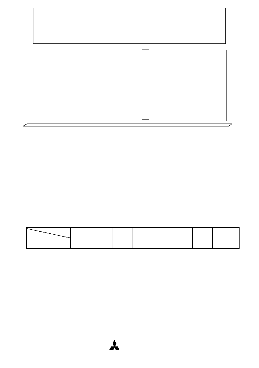
BLOCK DIAGRAM (8MB)
FUNCTION TABLE
M o d e
R E G #
C E 1 #
C E 2 #
O E #
W E #
A 0
I / O ( D 1 5 ~ D 8 )
I / O ( D 7 ~ D 0 )
I
C C
S t a n d b y
X
H
H
X
X
X
H i g h - i m p e d a n c e
H i g h - i m p e d a n c e
S t a n d b y
R e a d A ( 1 6 b i t ) c o m m o n
H
L
L
L
H
X
O d d B y t e D a t a o u t
E v e n B y t e D a t a o u t
A c t i v e
W r i t e A ( 1 6 b i t ) c o m m o n
H
L
L
H
L
X
O d d B y t e D a t a i n
E v e n B y t e D a t a i n
A c t i v e
R e a d B ( 8 b i t ) c o m m o n
H
L
H
L
H
L
H i g h - i m p e d a n c e
E v e n B y t e D a t a o u t
A c t i v e
H
L
H
L
H
H
H i g h - i m p e d a n c e
O d d B y t e D a t a o u t
A c t i v e
W r i t e B ( 8 b i t ) c o m m o n
H
L
H
H
L
L
H i g h - i m p e d a n c e
E v e n B y t e D a t a i n
A c t i v e
H
L
H
H
L
H
H i g h - i m p e d a n c e
O d d B y t e D a t a i n
A c t i v e
R e a d C ( 8 b i t ) c o m m o n
H
H
L
L
H
X
O d d B y t e D a t a o u t
H i g h - i m p e d a n c e
A c t i v e
W r i t e C ( 8 b i t ) c o m m o n
H
H
L
H
L
X
O d d B y t e D a t a i n
H i g h - i m p e d a n c e
A c t i v e
O u t p u t d i s a b l e
X
X
X
H
H
X
H i g h - i m p e d a n c e
H i g h - i m p e d a n c e
A c t i v e
R e a d A ( 1 6 b i t ) a t t r i b u t e
L
L
L
L
H
X
D a t a o u t ( u n k n o w n )
D a t a o u t ( F F h )
A c t i v e
R e a d B ( 8 b i t ) a t t r i b u t e
L
L
H
L
H
L
H i g h - i m p e d a n c e
D a t a o u t ( F F h )
A c t i v e
L
L
H
L
H
H
H i g h - i m p e d a n c e
D a t a o u t ( u n k n o w n )
A c t i v e
R e a d C ( 8 b i t ) a t t r i b u t e
L
H
L
L
H
X
D a t a o u t ( u n k n o w n )
H i g h - i m p e d a n c e
A c t i v e
N o t e 1 : H = V
I H
, L = V
I L ,
X = V
I H
o r V
I L
A22
A21
A20
A0
A19
A18
A17
A16
A15
A14
A13
A12
A11
A10
A9
A8
A7
A6
A5
A4
A3
A2
A1
D15
D14
D13
D12
D11
D10
D9
D8
D7
D6
D5
D4
D3
D2
D1
D0
BVD2
WE#
OE#
CE1#
CE2#
REG#
WP#
WRITE ROTECT
ON
OFF
CD1#
CD2#
19
16
BR2325
V
CC
VOLTAGE DETECTOR
&
POWER CONTROLLER
MODE
CONTROL
LOGIC
ADDRESS-
BUS
BUFFERS
ADDRESS-
DECODER
COMMON
MEMORY
4Mbit SRAM
◊
16
CS#
DATA-BUS
BUFFERS
GND
OE#
WE#
TO INTERNAL
POWER SUPPLY
16
BVD1

M I T S U B I S H I M E M O R Y C A R D
STATIC RAM CARDS
MITSUBISHI
ELECTRIC
4/9
ABSOLUTE MAXIMUM RATINGS
S y m b o l
P a r a m e t e r
C o n d i t i o n s
R a t i n g s
U n i t
V
C C
S u p p l y v o l t a g e
- 0 . 3 ~ 6 . 0
V
V i
I n p u t v o l t a g e
W i t h r e s p e c t t o G N D
- 0 . 3 ~ V
C C
+ 0 . 3
V
V
o
O u t p u t v o l t a g e
0 ~ V
C C
V
T
o p r 1
O p e r a t i n g t e m p e r a t u r e 1
R e a d , W r i t e , O p e r a t i o n
L C s e r i e s 0 ~ 7 0
∞ C
L S s e r i e s - 2 0 ~ 7 0
∞ C
T
o p r 2
O p e r a t i n g t e m p e r a t u r e 2
D a t a r e t e n t i o n
L C s e r i e s 0 ~ 7 0
∞ C
L S s e r i e s - 2 0 ~ 7 0
∞ C
T
s t g
S t o r a g e t e m p e r a t u r e
- 3 0 ~ 8 0
∞ C
RECOMMENDED OPERATING CONDITIONS (LC series Ta= 0~55∞C, unless otherwise noted)
( L S s e r i e s T a = - 2 0 ~ 7 0 ∞ C , u n l e s s o t h e r w i s e n o t e d )
L i m i t s
M i n .
T y p .
M a x .
V
C C
V
C C
s u p p l y v o l t a g e
4 . 5 0
5 . 0
5 . 2 5
V
G N D
S y s t e m g r o u n d
0
V
V
I H
H i g h i n p u t v o l t a g e
3 . 5
V
C C
V
V
I L
L o w i n p u t v o l t a g e
0
0 . 8
V
ELECTRICAL CHARACTERISTICS
( L C s e r i e s T a = 0 ~ 5 5 ∞ C , V
C C
= 4 . 5 0 ~ 5 . 2 5 V , u n l e s s o t h e r w i s e n o t e d )
( L S s e r i e s T a = - 2 0 ~ 7 0 ∞ C , V
C C
= 4 . 5 0 ~ 5 . 2 5 V , u n l e s s o t h e r w i s e n o t e d )
L i m i t s
M i n .
T y p .
M a x .
V
O H
H i g h o u t p u t v o l t a g e
I
O H
= - 1 . 0 m A , O t h e r o u t p u t s
2 . 4
V
V
O L
L o w o u t p u t v o l t a g e
I
O L
= 2 m A
0 . 4
V
I
I H
H i g h i n p u t c u r r e n t
V
I
= V
C C
V
1 0
µ A
I
I L
L o w i n p u t c u r r e n t
V
I
= 0 V
C E 1 # , C E 2 # , W E # , O E # , R E G #
- 1 0
- 7 0
µ A
O t h e r i n p u t s
- 1 0
I
O Z H
H i g h o u t p u t c u r r e n t
C E 1 # = C E 2 # = V
I H
o r O E # = V
I H
W E # = V
I H
,
1 0
µ A
i n o f f s t a t e
V
O
= V
C C
I
O Z L
L o w o u t p u t c u r r e n t
C E 1 # = C E 2 # = V
I H
o r O E # = V
I H
W E # = V
I H
,
- 1 0
µ A
i n o f f s t a t e
V
O
= 0 V
I
C C
1 ∑ 1
A c t i v e s u p p l y
C E # = V
I L
, o t h e r i n p u t s V
I H
o r
1 6 b i t
2 8 0
m A
c u r r e n t 1
V
I L
, O u t p u t s = o p e n
8 b i t
2 0 0
I
C C
1 ∑ 2
A c t i v e s u p p l y
C E #
0 . 2 V , o t h e r i n p u t s
1 6 b i t
2 7 0
m A
c u r r e n t 2
0 . 2 V o r
V
C C
- 0 . 2 V , O u t p u t s = o p e n
8 b i t
1 9 0
I
C C
2 ∑ 1
Standby supply current 1
C E 1 # = C E 2 # = V
I H
o t h e r i n p u t s = V
I H
o r V
I L
1 0
m A
I
C C
2 ∑ 2
Standby supply current 2
C E 1 # = C E 2 #
V
C C
- 0 . 2 V
o t h e r i n p u t s
0 . 2 V o r
V
C C
- 0 . 2 V
1
m A
V B D E T 1
B a t t e r y d e t e c t
V c c = 5 V , T a = 2 5
∞ C
V
r e f e r e n c e v o l t a g e 1
¨
V B D E T 2
B a t t e r y d e t e c t
V c c = 5 V , T a = 2 5
∞ C
V
r e f e r e n c e v o l t a g e 2
¨
N o t e 2 : C u r r e n t s f l o w i n g i n t o t h e I C a r e t a k e n a s p o s i t i v e ( u n s i g n e d ) .
3 : T y p i c a l v a l u e s a r e m e a s u r e d a t V
C C
= 5 V , T a = 2 5 ∞ C .
¨
P i n a s s e r t e d w h e n b a t t e r y v o l t a g e d r o p s b e l o w s p e c i f i e d l e v e l .
U n i t
2.37
2.65
S y m b o l
P a r a m e t e r
Unit
2.75
2.47
2.55
2.27
S y m b o l
P a r a m e t e r
Test conditions

M I T S U B I S H I M E M O R Y C A R D
STATIC RAM CARDS
MITSUBISHI
ELECTRIC
5/9
CAPACITANCE
L i m i t s
M i n .
T y p .
M a x .
C
I
I n p u t c a p a c i t a n c e
V
I
= G N D , V
I
= 2 5 m V r m s
3 0
p F
f = 1 M H
Z
, T a = 2 5 ∞ C
C
O
O u t p u t c a p a c i t a n c e
V
O
= G N D , V
O
= 2 5 m V r m s f = 1 M H
Z
,
T a = 2 5 ∞ C
2 0
p F
N o t e 4 : T h e s e p a r a m e t e r s a r e n o t 1 0 0 % t e s t e d .
SWITCHING CHARACTERISTICS
Read Cycle (LC series Ta= 0~55∞C, V
C C
= 4 . 5 0 ~ 5 . 2 5 V , u n l e s s o t h e r w i s e n o t e d )
( L S s e r i e s T a = - 2 0 ~ 7 0 ∞ C , V
C C
= 4 . 5 0 ~ 5 . 2 5 V , u n l e s s o t h e r w i s e n o t e d )
L i m i t s
Symbol
Parameter
M i n .
T y p .
M a x .
Unit
t
C R
R e a d c y c l e t i m e
2 0 0
n s
t
a
( A )
A d d r e s s a c c e s s t i m e
2 0 0
n s
t
a
( C E )
C a r d e n a b l e a c c e s s t i m e
2 0 0
n s
t
a
( O E )
O u t p u t e n a b l e a c c e s e t i m e
1 0 0
n s
t
d i s
( C E )
O u t p u t d i s a b l e t i m e ( f r o m C E # )
9 0
n s
t
d i s
( O E )
O u t p u t d i s a b l e t i m e ( f r o m O E # )
9 0
n s
t
e n
( C E )
O u t p u t e n a b l e t i m e ( f r o m C E # )
5
n s
t
e n
( O E )
O u t p u t e n a b l e t i m e ( f r o m O E # )
5
n s
t
V
( A )
D a t a v a l i d t i m e ( a f t e r a d d r e s s c h a n g e )
0
n s
TIMING REQUIREMENTS
Write Cycle(LC series Ta= 0~55∞C, V
C C
= 4 . 5 0 ~ 5 . 2 5 V , u n l e s s o t h e r w i s e n o t e d )
( L S s e r i e s T a = - 2 0 ~ 7 0 ∞ C , V
C C
= 4 . 5 0 ~ 5 . 2 5 V , u n l e s s o t h e r w i s e n o t e d )
L i m i t s
Symbol
Parameter
M i n .
T y p .
M a x .
Unit
t
C W
W r i t e c y c l e t i m e
2 0 0
n s
t
w ( W E )
W r i t e p u l s e w i d t h
1 2 0
n s
t
s u ( A )
A d d r e s s s e t u p t i m e
2 0
n s
t
s u ( A - W E H )
A d d r e s s s e t u p t i m e w i t h r e s p e c t t o W E # h i g h
1 4 0
n s
t
s u ( C E - W E H )
C a r d e n a b l e s e t u p t i m e w i t h r e s p e c t t o W E # h i g h
1 4 0
n s
t
s u ( D - W E H )
D a t a s e t u p t i m e w i t h r e s p e c t t o W E # h i g h
6 0
n s
t
h ( D )
D a t a h o l d t i m e
3 0
n s
t
r e c ( W E )
W r i t e r e c o v e r y t i m e
3 0
n s
t
d i s ( W E )
O u t p u t d i s a b l e t i m e ( f r o m W E # )
9 0
n s
t
d i s ( O E )
O u t p u t d i s a b l e t i m e ( f r o m O E # )
9 0
n s
t
e n ( W E )
O u t p u t e n a b l e t i m e ( f r o m W E # )
5
n s
t
e n ( O E )
O u t p u t e n a b l e t i m e ( f r o m O E # )
5
n s
t
s u ( O E - W E )
O E # s e t u p t i m e w i t h r e s p e c t t o W E # l o w
1 0
n s
t
h ( O E - W E )
O E # h o l d t i m e w i t h r e s p e c t t o W E # h i g h
1 0
n s
Symbol
Unit
Parameter
Test conditions