 | –≠–ª–µ–∫—Ç—Ä–æ–Ω–Ω—ã–π –∫–æ–º–ø–æ–Ω–µ–Ω—Ç: MAX2822 | –°–∫–∞—á–∞—Ç—å:  PDF PDF  ZIP ZIP |
General Description
The MAX2822 single-chip transceiver is designed for
802.11b (11Mbps) applications operating in the 2.4GHz
to 2.5GHz ISM band. The transceiver includes all the
circuitry required to implement an 802.11b RF-to-base-
band transceiver solution, including the power amplifi-
er, transmit/receive switch, and 50
matching. The fully
integrated receive path, transmit path, VCO, frequency
synthesis, and baseband/control interface provide all
the required active RF circuitry. Only a small number of
passive components are needed to form the complete
radio front-end solution.
The IC eliminates the need for external IF SAW and RF
image-reject filters by utilizing a direct-conversion radio
architecture and monolithic baseband filters for both
receiver and transmitter. It is specifically optimized for
802.11b (11Mbps CCK) and 22Mbps PBCCTM applica-
tions. The baseband filtering and Rx and Tx signal
paths support the CCK modulation scheme for BER =
10
-5
at the required sensitivity levels.
The transceiver is suitable for the full range of 802.11b
data rates (1Mbps, 2Mbps, 5.5Mbps, and 11Mbps) as
well as the higher-rate 22Mbps PBCC standard. The
MAX2822 is available in the very small 7mm x 7mm 48-
lead QFN or thin QFN packages. The small solution size
makes it ideal for small form-factor 802.11b applications
such as PDAs, SmartPhones, and embedded modules.
Applications
802.11b PDAs and SmartPhones
802.11b Embedded Modules
802.11b PC Cards, Mini-PCI Cards
Features
2.4GHz to 2.5GHz ISM Band Operation
802.11b (11Mbps CCK and 22Mbps PBCC) PHY
Compatible
Integrated +17dBm PA
Integrated PA Power Detector
Integrated Transmit/Receive Switch
Complete RF-to-Baseband Transceiver
Direct Up/Down Conversion
Monolithic Low-Phase-Noise VCO
Integrated Baseband Lowpass Filters
Integrated PLL with 3-Wire Serial Interface
Digital Bias Control for PA
Transmit Power Control
Receive Baseband AGC
Complete Baseband Interface
Digital Tx/Rx Mode Control
-95dBm Rx Sensitivity at 1Mbps
-85dBm Rx Sensitivity at 11Mbps
Single +2.7V to +3.0V Supply
2µA Shutdown Mode
Very Small 48-Pin QFN Package
MAX2822
2.4GHz 802.11b Zero-IF Transceiver
with Integrated PA and Tx/Rx Switch
________________________________________________________________ Maxim Integrated Products
1
Ordering Information
19-2884; Rev 0; 7/03
For pricing, delivery, and ordering information, please contact Maxim/Dallas Direct! at
1-888-629-4642, or visit Maxim's website at www.maxim-ic.com.
Pin Configuration/Functional Diagram appears at end of
data sheet.
PBCC is a trademark of Texas Instruments, Inc.
PART
TEMP RANGE
PIN-PACKAGE
MAX2822EGM
-40
∞C to +85∞C
48 QFN
MAX2822ETM
-40
∞C to +85∞C
48 Thin QFN
EVALUATION KIT
AVAILABLE
MAX2822
2.4GHz 802.11b Zero-IF Transceiver
with Integrated PA and Tx/Rx Switch
2
_______________________________________________________________________________________
ABSOLUTE MAXIMUM RATINGS
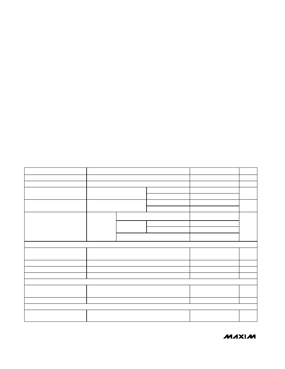
DC ELECTRICAL CHARACTERISTICS
(MAX2822 EV kit: V
CC
= +2.7V to +3.0V, RF_GAIN = V
IH
, 0V
V
TX_GC
+2.0V, 0V V
RX_AGC
+2.0V, R
BIAS
= 12k
, no input sig-
nals at RF and baseband inputs, RF I/O terminated into 50
though a 2:1 balun, receiver baseband outputs are open, transmitter
baseband inputs biased at +1.2V, registers set to default power-up settings, T
A
= -40∞C to +85∞C, unless otherwise noted. Typical
values are for V
CC
= +2.7V, T
A
= +25∞C, unless otherwise noted.) (Note 1)
Stresses beyond those listed under "Absolute Maximum Ratings" may cause permanent damage to the device. These are stress ratings only, and functional
operation of the device at these or any other conditions beyond those indicated in the operational sections of the specifications is not implied. Exposure to
absolute maximum rating conditions for extended periods may affect device reliability.
V
CC
Pins to GND ...................................................-0.3V to +3.6V
RF I/O: RFP, RFN (current into pin).....................................50mA
Baseband Inputs: TX_BBIP, TX_BBIN, TX_BBQP,
TX_BBQN to GND ..................................-0.3V to (V
CC
+ 0.3V)
Baseband Outputs: RX_BBIP, RX_BBIN, RX_BBQP,
RX_BBQN to GND ..................................-0.3V to (V
CC
+ 0.3V)
Analog Inputs: RX_AGC, TX_GC, TUNE, ROSCN,
ROSCP to GND ......................................-0.3V to (V
CC
+ 0.3V)
Analog Outputs: PWR_DET, CP_OUT
to GND....................................................-0.3V to (V
CC
+ 0.3V)
Digital Inputs: RX_ON, TX_ON, SHDNB, CSB, SCLK,
DIN, RF_GAIN, RX_1K to GND...............-0.3V to (V
CC
+ 0.3V)
Bias Voltages: RBIAS, BYP ..................................+0.9V to +1.5V
Short-Circuit Duration Digital Output: DOUT ..........................10s
RF Input Power ...............................................................+10dBm
Continuous Power Dissipation (T
A
= +70∞C)
48-Lead QFN (derate 27.0mW/
∞C above +70∞C) ......2162mW
Operating Temperature Range ...........................-40∞C to +85∞C
Junction Temperature ......................................................+150∞C
Storage Temperature Range .............................-65∞C to +160∞C
Lead Temperature (soldering, 10s) .................................+300∞C
PARAMETERS
CONDITIONS
MIN
TYP
MAX
UNITS
Supply Voltage
2.7
3.0
V
Shutdown Current
SHDNB = V
IL
, RX_ON = V
IL
, TX_ON = V
IL
2
50
µA
T
A
= +25∞C
25
35
Standby-Mode Supply Current
SHDNB = V
IH
, RX_ON = V
IL
,
TX_ON = V
IL
T
A
= -40∞C to +85∞C
40
mA
T
A
= +25∞C
80
100
Receive-Mode Supply Current
SHDNB = V
IH
, RX_ON = V
IH
,
TX_ON = V
IL
T
A
= -40∞C to +85∞C
110
mA
P
OUT
= +3dBm
98
T
A
= +25∞C
157
175
P
OUT
=
+12dBm
T
A
= -40∞C to +85∞C
185
Transmit-Mode Supply Current
S H DN B = V
IH
,
RX _ON = V
IL
,
TX _ON = V
IH
,
b i as r eg i ster s
set as i n Tab l e 9
P
OUT
= +17dBm
220
mA
LOGIC INPUTS: SHDNB, RX_ON, TX_ON, SCLK, DIN, CSB, RF_GAIN
Digital Input Voltage High (V
IH
)
V
CC
-
0.5
V
Digital Input Voltage Low (V
IL
)
0.5
V
Digital Input Current High (I
IH
)
-5
+5
µA
Digital Input Current Low (I
IL
)
-5
+5
µA
LOGIC OUTPUT: DOUT
Digital Output Voltage High (V
OH
)
Sourcing 100µA
V
CC
-
0.5
V
Digital Output Voltage Low (V
OL
)
Sinking 100µA
0.5
V
ANALOG OUTPUT: PWR_DET
Power-Detector Output
Impedance
400

MAX2822
2.4GHz 802.11b Zero-IF Transceiver
with Integrated PA and Tx/Rx Switch
_______________________________________________________________________________________
3
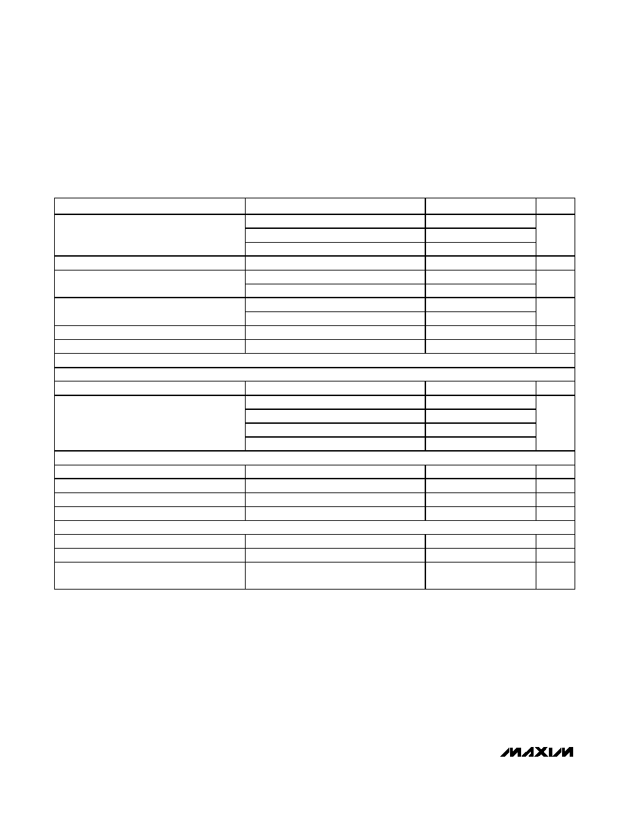
DC ELECTRICAL CHARACTERISTICS (continued)
(MAX2822 EV kit: V
CC
= +2.7V to +3.0V, RF_GAIN = V
IH
, 0V
V
TX_GC
+2.0V, 0V V
RX_AGC
+2.0V, R
BIAS
= 12k
, no input sig-
nals at RF and baseband inputs, RF I/O terminated into 50
though a 2:1 balun, receiver baseband outputs are open, transmitter
baseband inputs biased at +1.2V, registers set to default power-up settings, T
A
= -40∞C to +85∞C, unless otherwise noted. Typical
values are for V
CC
= +2.7V, T
A
= +25∞C, unless otherwise noted.) (Note 1)
PARAMETERS
CONDITIONS
MIN
TYP
MAX
UNITS
RX BASEBAND I/O
RX_AGC Input Resistance
0V
V
RX_AGC
+2.0V
50
k
Rx I/Q Common-Mode Voltage
1.25
V
Rx I/Q Output DC Offsets
3
limit
±15
mV
TX BASEBAND I/O
TX BB Input Common-Mode
Range
1.0
1.2
1.4
V
TX BBI and BBQ Input Bias
Current
-10
µA
TX BB Input Impedance
Differential resistance
100
k
TX_GC Input Bias Current
0V
V
TX_GC
+2.0V
10
µA
TX_GC Input Impedance
Resistance
250
k
REFERENCE OSCILLATOR INPUT
Reference Oscillator Input
Impedance
20
k
VOLTAGE REFERENCE
Reference Voltage
I
LOAD
= ±2mA
1.10
1.20
1.30
V
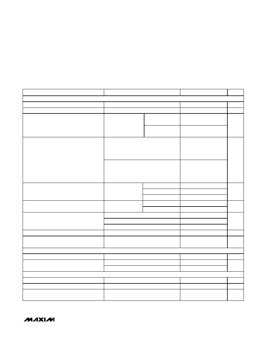
AC ELECTRICAL CHARACTERISTICS--RECEIVE MODE
(MAX2822 EV kit: V
CC
= +2.7V to +3.0V, f
RF
and f
LO
= 2400MHz to 2499MHz, f
OSC
= 22MHz or 44MHz, receive baseband output
levels = 500mV
P-P
, V
SHDNB
= V
RX_ON
= V
IH, VTX_ON
= V
IL, VCSB
= V
IH, VSCLK
= V
DIN
= V
IL
, V
RF_GAIN
= V
IH
, 0V
V
RX_AGC
+2.0V,
R
BIAS
= 12k
, I
CP
= +2mA, BW
PLL
= 45kHz, registers set to default power-up settings, T
A
= +25∞C, unless otherwise noted. Typical
values are for V
CC
= +2.7V, f
LO
= 2437MHz, f
OSC
= 22MHz, unless otherwise noted.) (Note 2)
PARAMETER
CONDITIONS
MIN
TYP
MAX
UNITS
RECEIVER CASCADED PERFORMANCE (RF INPUT TO BASEBAND OUTPUT)
RF Frequency Range
2400
2499
MHz
LO Frequency Range
2400
2499
MHz
T
A
= +25∞C
97
105
RF_GAIN = V
IH
,
V
RX_AGC
= 0V
T
A
= -40∞C to +85∞C
95
RF_GAIN = V
IH
, V
RX_AGC
= +2.0V
35
RF_GAIN = V
IL
, V
RX_AGC
= 0V
75
Voltage Gain (Note 3)
RF_GAIN = V
IL
, V
RX_AGC
= +2.0V
3
dB
RF Gain Step
From RF_GAIN = V
IH
to RF_GAIN = V
IL
32
dB
MAX2822
2.4GHz 802.11b Zero-IF Transceiver
with Integrated PA and Tx/Rx Switch
4
_______________________________________________________________________________________
AC ELECTRICAL CHARACTERISTICS--RECEIVE MODE (continued)
(MAX2822 EV kit: V
CC
= +2.7V to +3.0V, f
RF
and f
LO
= 2400MHz to 2499MHz, f
OSC
= 22MHz or 44MHz, receive baseband output
levels = 500mV
P-P
, V
SHDNB
= V
RX_ON
= V
IH, VTX_ON
= V
IL, VCSB
= V
IH, VSCLK
= V
DIN
= V
IL
, V
RF_GAIN
= V
IH
, 0V
V
RX_AGC
+2.0V,
R
BIAS
= 12k
, I
CP
= +2mA, BW
PLL
= 45kHz, registers set to default power-up settings, T
A
= +25∞C, unless otherwise noted. Typical
values are for V
CC
= +2.7V, f
LO
= 2437MHz, f
OSC
= 22MHz, unless otherwise noted.) (Note 2)
PARAMETER
CONDITIONS
MIN
TYP
MAX
UNITS
RF_GAIN = V
IH
, RX gain
80dB
5.5
6.0
RF_GAIN = V
IH
, RX gain = 50dB
8
DSB Noise Figure (Note 4)
RF_GAIN = V
IL
, RX gain = 50dB
35
dB
Adjacent Channel Rejection
RX gain = 70dB (Note 5)
45
dB
RF_GAIN = V
IH
, RX gain = 80dB
-13
Input Third-Order Intercept Point (Note 6)
RF_GAIN = V
IL
, RX gain = 50dB
+19
dBm
RF_GAIN = V
IH
, RX gain = 80dB
+23
Input Second-Order Intercept Point (Note 7)
RF_GAIN = V
IL
, RX gain = 50dB
+60
dBm
LO Leakage
At balun input
-65
dBm
Input Return Loss
15
dB
RECEIVER BASEBAND
BASEBAND FILTER RESPONSE
-3dB Frequency
Default bandwidth setting BW(2:0) = (010)
7
MHz
At 12.5MHz
40
At 16MHz
65
At 20MHz
70
Attenuation Relative to Passband
At 25MHz
85
dB
BASEBAND OUTPUT CHARACTERISTICS
Rx I/Q Gain Imbalance
3
limit
±1
dB
Rx I/Q Phase Quadrature Imbalance
3
limit
±5
D eg r ees
Rx I/Q Output 1dB Compression
Differential voltage into 5k
1
VP-P
Rx I/Q Output THD
V
OUT
= 500mV
P-P
at 5.5MHz, Z
L
= 5k
||5pF
-35
dBc
BASEBAND AGC AMPLIFIER
AGC Range
V
RX_AGC
= 0 to +2.0V
70
dB
AGC Slope
Peak gain slope
60
dB/V
AGC Response Time
20dB gain step (80dB to 60dB),
settling to
±1dB
2
µs
MAX2822
2.4GHz 802.11b Zero-IF Transceiver
with Integrated PA and Tx/Rx Switch
_______________________________________________________________________________________
5
AC ELECTRICAL CHARACTERISTICS--TRANSMIT MODE
(MAX2822 EV kit, characteristics relative to RFP/RFN: V
CC
= +2.7V to +3.0V, f
RF
and f
LO
= 2400MHz to 2499MHz, f
OSC
= 22MHz or
44MHz, transmit baseband input signal: 500mV
P-P
at 5.5MHz, V
SHDNB
= V
RX_ON
= V
IL, VTX_ON
= V
IH, VCSB
= V
IH
, V
SCLK
= V
DIN
=
V
IL
, V
RF_GAIN
= V
IH
, 0V
V
TX_AGC
+2.0V, R
BIAS
= 12k
, ICP = +2mA, BW
PLL
= 45kHz, baseband inputs DC biased to +1.2V, reg-
isters set to default power-up settings, measurements taken within 1s of TXON rising edge, T
A
= +25∞C, unless otherwise noted.
Typical values are for V
CC
= +2.7V, f
LO
= 2437MHz, f
OSC
= 22MHz, unless otherwise noted.) (Note 2)
PARAMETER
CONDITIONS
MIN
TYP
MAX
UNITS
TRANSMIT SIGNAL PATH: BASEBAND INPUT TO RF OUTPUT
RF Output Frequency Range
2400
2499
MHz
LO Output Frequency Range
2400
2499
MHz
T
A
= +25∞C
+ 16.5
+ 17.5
Tx RF Output Power
11Mb p s C C K si g nal ,
AC PR ( ad j )
- 30d Bc,
AC PR ( al t)
- 50d Bc
( N ote 4)
T
A
= - 40∞C to + 85∞C +
15.5
dBm
Adjacent (adj):
-22MHz
f
OFFSET
-11MHz,
11MHz
f
OFFSET
22MHz,
P
OUT
= + 16.5d Bm
-33
Tx RF ACPR (Note 8)
Alternate (alt):
-33MHz
f
OFFSET
< -22MHz,
22MHz < f
OFFSET
33MHz,
P
OUT
= + 16.5d Bm
-56
dBc
Unwanted sideband
-40
LO signal
-30
In-Band Spurious Signals Relative to Carrier
f
RF
= 2400MHz to
2483MHz
(Note 9)
Spurs >
±22MHz
-80
dBc
2
◊ f
RF
-45
Tx RF Harmonics
11Mbps CCK at
+16.5dBm
3
◊ f
RF
-30
dBm
< 2400MHz
-50
2500MHz to 3350MHz
-35
Tx RF Spurious Signal Emissions
(Outside 2400MHz to 2483.5MHz)
Nonharmonic Signals
> 3350MHz
-40
dBm
Tx RF Output Noise
f
OFFSET
22MHz, 0V V
TX_GC
+2.0V
-125
dBm/Hz
Tx RF Output Return Loss
100
balanced output impedance,
P
OUT
= +17dBm
10
dB
Tx BASEBAND FILTER RESPONSE
-3dB Frequency
10
MHz
At 22MHz
25
Attenuation Relative to Passband
At 44MHz
50
dB
Tx GAIN-CONTROL CHARACTERISTICS
Gain-Control Range
0V
V
TX_GC
+2.0V
20
dB
Gain-Control Slope
Peak gain slope
30
dB/V
Gain-Control Response Time
V
TX_GC
= +2.0V to 0V step, settled to within
±1dB
0.3
µs