Evaluates: MAX2360/MAX2362/MAX2364
MAX2360 Evaluation Kit
________________________________________________________________ Maxim Integrated Products
1
__________________Pin Configuration
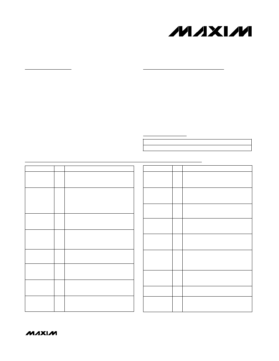
__________Typical Operating Circuit
General Description
The MAX2360 evaluation kit (EV kit) simplifies testing of
the MAX2360/MAX2362/MAX2364. The EV kit provides
50
SMA connectors for all RF inputs and outputs. A
varactor-based tank circuit is provided for the on-chip
voltage-controlled oscillator (VCO) and can be tuned
by a potentiometer or external voltage, or phase locked
with an on-chip PLL. I/Q baseband inputs come stan-
dard with BNC connectors.
The EV kit allows evaluation of the MAX2360/MAX2362/
MAX2364s' variable-gain amplifier (VGA), I/Q IF modu-
lator, IF VGA, RF upconverter, dual-band IF VCOs, dual
synthesizer, 3-wire programming interface, and power-
management features.
The MAX2360 EV kit also allows evaluation of the single-
band MAX2362/MAX2364, as they are subsets of the
MAX2360.
Features
o SPITM/QSPITM/MICROWIRETM Compatible
o Differential and Single-Ended Baseband Inputs
o Single-Supply Operation
o 50 SMA Connectors on All RF Ports
o BNC Connectors for Baseband Inputs
o Low-Power Shutdown Mode
o PC Control Software Available at www.maxim-ic.com
19-1651; Rev 1; 5/01
PART
MAX2360EVKIT
-40�C to +85�C
TEMP. RANGE
IC PACKAGE
48 TQFP
Ordering Information
Component List
1�F �10% ceramic capacitors (0805)
Murata GRM40X7R105K010 or
Taiyo Yuden LMK212BJ105KG
3
C9, C21, C94
1000pF �10% ceramic caps (0402)
Murata GRM36X7R102K50 or
Taiyo Yuden UMK105B102KW
6
C7, C10, C19,
C43, C52, C63
2.4pF �0.1pF ceramic capacitor (0402)
Murata GRM36COG2R4B050 or
Taiyo Yuden EVK105CH2R4JW
1
C6
DESIGNATION
Not installed
0
C5, C13, C14,
C26, C27,
C65, C66
0.01�F �10% ceramic caps (0402)
Murata GRM36X7R103K016 or
Taiyo Yuden EMK105BJ103KV
12
C4, C8, C11,
C15, C17, C18,
C32�C35,
C55, C75
33pF �5% ceramic capacitors (0402)
Murata GRM36COG330J050 or
Taiyo Yuden UMK105CH330JW
2
C3, C41
100pF �5% ceramic capacitors (0402)
Murata GRM36COG101J050 or
Taiyo Yuden UMK105CH101JW
14
C2, C16, C20,
C31, C39, C40,
C57, C60, C64,
C67, C68, C76,
C78, C80
3pF �0.1pF ceramic capacitor (0402)
Murata GRM36COG030B050 or
Taiyo Yuden EVK105CH030JW
1
C1
DESCRIPTION
QTY
7pF �0.5pF ceramic capacitor (0402)
Murata GRM36COG070D50 or
Taiyo Yuden UMK105CH070DW
1
C48
9.1pF �0.25pF ceramic caps (0402)
Murata GRM36COG9R1C050
2
C47, C50
15pF �5% ceramic capacitors (0402)
Murata GRM36COG150J050 or
Taiyo Yuden UMK105CH150JW
3
C44, C45, C46
0.1�F �10% ceramic capacitors (0402)
Murata GRM36X5R104K010 or
Taiyo Yuden LMK105BJ104KV
12
C38, C42, C58,
C79, C88, C89,
C91, C92, C93,
C95, C96, C97
3300pF �10% ceramic caps (0402)
Murata GRM36X7R332K050 or
Taiyo Yuden UMK105B332KW
2
C30, C36
0.033�F �10% ceramic caps (0402)
Murata GRM36X7R333K010 or
Taiyo Yuden LMK105BJ333KV
3
C28, C29, C37
12pF �5% ceramic capacitors (0402)
Murata GRM36COG120J050 or
Taiyo Yuden UMK105CH120JW
2
C24, C25
18pF �5% ceramic capacitors (0402)
Murata GRM36COG180J050 or
Taiyo Yuden UMK105CH180JW
2
C22, C23
4.3pF �0.1pF ceramic capacitor (0402)
Murata GRM36COG4R3B050 or
Taiyo Yuden EVK105CH4R3JW
1
C12
DESIGNATION
DESCRIPTION
QTY
SPI and QSPI are trademarks of Motorola, Inc.
MICROWIRE is a trademark of National Semiconductor Corp.
For pricing, delivery, and ordering information, please contact Maxim/Dallas Direct! at
1-888-629-4642, or visit Maxim's website at www.maxim-ic.com.

Evaluates: MAX2360/MAX2362/MAX2364
MAX2360 Evaluation Kit
2
_______________________________________________________________________________________
Component List (continued)
L4
1
10nH �5% inductor (0603)
Coilcraft 0603CS-10NXJBC
L5, L16, L19
3
220nH �5% inductors (0603)
Coilcraft 0603CS-R22XJBC
L6
1
2.2nH �0.3nH inductor (0402)
Murata LQG10A2N2S00
L9
1
39nH �5% inductor (0603)
Coilcraft 0603CS-39NXJBC
JP1
1
20-pin header (2x10), 0.1in centers
JP2
1
5-pin header, 0.1in centers
JU1�JU4 ,
JU6�JU10,
JU12
10
2-pin headers
L1
1
8.7nH �5% inductor (0603)
Coilcraft 0603CS-8N7XJBC
L2, L3
2
100nH �5% inductors (0603)
Coilcraft 0603CS-R10XJBC
D3
0
Not installed
FL1
1
130.38MHz LC filter
Murata LFSH30N32M0130A
GND, GND,
RBIAS, VBAT,
VGC, VREG
6
Test points
Mouser 151-203
I-, Q-
2
BNC jacks (PC mount, female)
A/D Electronics 580-002-00
IFINH, IFLO,
IFOUTH, LOH,
LOL, REF,
RFH0, RFH1,
RFL
9
SMA connectors (PC edge mount)
EFJohnson 142-0701-801
QTY
DESCRIPTION
DESIGNATION
C49
1
2.7pF �0.1pF ceramic capacitor (0402)
Murata GRM36COG2R7B050 or
Taiyo Yuden EVK105CH2R7JW
C51
1
1.5pF �0.1pF ceramic capacitor (0402)
Murata GRM36COG1R5B050 or
Taiyo Yuden EVK105CH1R5BW
C53, C54
2
10pF �5% ceramic capacitors (0402)
Murata GRM36COG100J050 or
Taiyo Yuden UMK105CH100JW
C77
1
10�F, 10V tantalum capacitor
AVX TAJB106M010
D1, D2
2
Varactor diodes
Alpha Industries SMV1255-003
L10, L11
2
22nH �5% inductors (0603)
Coilcraft 0603CS-22NXJBC
MAX2360 EV kit software
1
None
U2
0
Not installed
QTY
DESCRIPTION
INTF2300 board
1
None
None
1
MAX2360 EV kit data sheet
None
1
MAX2360/MAX2362/MAX2364
data sheet
DESIGNATION
None
1
MAX2360 PC board
None
8
Shunts for JU3, JU4, JU6�JU10, JU12
V2
1
967MHz VCO
Murata MQE-917-967
V1
1
1750MHz VCO
Murata MQE-925-1750
U1
1
MAX2360ECM (48-pin TQFP)
T5, T6
2
Balun transformers
Coilcraft TTWB2010
T2, T3
2
Balun transformers (B5F type)
TOKO 458DB-1011
R74
1
16.2k
�1% resistor (0603)
R53, R57
2
150
�5% resistors (0402)
R38, R60, R61,
R62, R67
0
Not installed (shorted with PC trace)
R41, R66
2
10k
�10% multiturn potentiometers
R43, R54, R56
3
100
�5% resistors (0402)
R3
1
51k
�5% resistor (0402)
R4, R5, R20,
R29, R30, R46
6
1k
�5% resistors (0402)
R6, R8, R14,
R16, R76
5
0
resistors (0402)
R9�R12, R15,
R17, R18, R19,
R33, R37, R39,
R65, R70�R73,
R75, R77
0
Not installed (open)
R31, R32, R35,
R36, R40, R64
6
10k
�5% resistors (0402)
Q1
0
Not installed
R1, R2, R7, R47
4
47k
�5% resistors (0402)

Quick Start
The MAX2360 EV kit is fully assembled and factory test-
ed. Follow the instructions in the Connections and
Setup section.
Test Equipment Required
This section lists the recommended test equipment to
verify the operation of the MAX2360. It is intended as a
guide only, and substitutions may be possible.
� One RF signal generator capable of delivering
-7dBm of output power in the 10MHz to 50MHz fre-
quency range (HP 8648A or equivalent) for the PLL
reference frequency
� An RF spectrum analyzer with optional CDMA per-
sonality (Rohde & Schwarz FSEA20 or equivalent)
� A power supply that can provide 250mA at +3.0V
� Low-noise power supply (HP 6236B or equivalent),
or voltage regulator
� Optionally, an additional voltage source for external
control of VGA functions
� I/Q arbitrary waveform generator or CDMA generator
(HP E4433B or equivalent)
� PC (486DX33 or better) with Win95
�
or Win98
�
operating system and an available parallel port
� INTF2300 interface board (supplied with EV kit)
Connections and Setup
This section provides step-by-step instructions for get-
ting the EV kit up and running in cellular and PCS
CDMA modes.
Cellular CDMA Mode
Perform the following steps to evaluate the MAX2360 in
the cellular CDMA mode:
1) Verify shunts JU4, JU6�JU10, and JU12 are in
place. Connect the cellular VCO module side of
JU2 to the low-noise power supply or a regulator.
This is to prevent excessive supply pushing, which
degrades the ACPR of narrow-band modulation
such as IS-136, even though the ACPR of CDMA-
modulated signals is not affected.
2) Connect the INTF2300 interface cable as shown in
Figure 7. Note: Pin 1 of the interface cable corre-
sponds to the red wire. Pin 1 is designated in
silkscreen on each of the PC boards.
3) Download the serial-interface control software at
www.maxim-ic.com/techsupport/other/htm and
install on a PC with a parallel port.
4) Connect a +2.85V power supply to the V
BAT
and
V
REG
terminals. The INTF2300 board derives its
power from the MAX2360 EV kit.
5) Connect a function generator to the REF port, con-
figured for a sine wave with a frequency of
19.68MHz and an amplitude of -13dBm.
6) Connect a CDMA baseband signal generator to the
I and Q ports using a BNC connector. Configure the
output for 200mV
RMS
. The EV kit includes trans-
formers at the I and Q inputs that do not pass sig-
nals below 50kHz. For evaluation of digital mode
with low-frequency content, bypass the transformer
as described in the Detailed Description.
7) Install and run Maxim CDMA control software.
Software is also available on the Web at
www.maxim-ic.com. On the IC selection form, click
on the MAX2360 control button.
8) With the MAX2360 control screen active, click on the
cellular CDMA preset located at the left of the
screen.
9) Click on the Send Data button for each of the con-
trol registers located at the right of the screen.
There are seven registers that need to be down-
loaded to the IC. The Lock LED on the screen
should be red, indicating lock.
10) Set the VGA control to 2.5VDC by rotating poten-
tiometer R66. Optionally, an external VGA control
voltage may be used by removing jumper JU4 and
applying a DC voltage to header VGC. Current con-
sumption is about 150mA. This includes the RF
VCO and the potentiometers.
11) Connect RFL to the spectrum analyzer. Configure a
Evaluates: MAX2360/MAX2362/MAX2364
MAX2360 Evaluation Kit
_______________________________________________________________________________________
3
Component Suppliers
803-626-3123
803-946-0690
AVX
617-933-2359
617-935-5150
Alpha Industries
SUPPLIER
FAX
PHONE
847-639-1469
847-639-6400
Coilcraft
708-699-1194
708-297-0070
Toko
408-573-4159
408-573-4150
Taiyo Yuden
949-852-2002
949-852-2001
Murata
402-474-4858
402-474-4800
EFJohnson
Win95 and Win98 are registered trademarks of Microsoft Corp.
Note: Please indicate that you are using the MAX2360 when
contacting these component suppliers.

Evaluates: MAX2360/MAX2362/MAX2364
spectrum analyzer to measure ACPR for reverse-
channel CDMA. Set the center frequency to
836MHz with a +10dBm reference level.
12) The output power should be about 7dBm after
accounting for cable and connector loss. The ACPR
at �885kHz offset should be -54dBc, and the ACPR
at �1.98MHz offset should be -70dBc.
Low-Band PCS CDMA Mode
Perform the following steps to evaluate the MAX2360 in
the PCS CDMA mode:
1) Connect the PCS VCO module side of JU3 to the
low-noise power supply or a regulator.
2) With the MAX2360 control screen active, click on
the PCS Low preset located at the left of the screen.
3) Click on the Send Data buttons for each of the con-
trol registers located at the right of the screen.
There are seven registers that need to be down-
loaded to the IC. The Lock LED on the screen
should be red, indicating lock.
4) Set the VGA control to 2.55VDC by rotating poten-
tiometer R66. Optionally, an external VGA control
voltage may be used by removing jumper JU4 and
applying a DC voltage to header VGC. Current con-
sumption is about 150mA. This includes the RF
VCO and the potentiometer.
5) Connect the RFH1 port to the spectrum analyzer.
Configure a spectrum analyzer to measure ACPR
for reverse-channel CDMA. Set the center frequen-
cy to 1880.38 MHz with a +10dBm reference level.
6) The output power should be about 7dBm after
accounting for cable and connector loss. The ACPR
at �1.25MHz offset should be -54dBc.
Adjustments and Control
VGA Adjust
The MAX2360 EV kit is configured with a 10k
trim pot-
entiometer for setting and adjusting the VGA gain. By
removing the two-pin shunt JU4, an external supply can
be used by directly connecting to header VGC. The
VGC voltage is filtered on the EV kit to minimize unde-
sired amplitude modulation.
Optional VCO External Adjust
The MAX2360 EV kit is configured with a 10k
trim pot-
entiometer for setting and adjusting the VCO tune volt-
age. Apply a two-pin shunt to JU1. Stuff a 0
resistor
for R33, and remove R38 to break the loop and remove
the charge-pump output. The VCO voltage must be
clean to minimize undesired frequency modulation.
Interface Control
The interface port is designed to use a 20-pin ribbon
cable (Figure 8); 10 pins are signal lines, and the other
10 pins are digital grounds. Pin 1 of the interface cable
is red. Pin 1 is also designated in silk screen on each of
the PC boards.
IDLE
A logic low on the IDLE pin shuts down everything
except the RF PLL and associated registers.
TXGATE
A logic low on the TXGATE pin shuts down everything
except the RF PLL, IF PLL, IF VCO, serial bus, and reg-
isters. This mode is used for gated transmission.
SHDN
A logic low on the SHDN pin powers down the entire
device, including registers and the serial interface.
Detailed Description
The following section covers the EV kit's circuit blocks
in detail (refer to the MAX2360/MAX2362/MAX2364
data sheet for additional information).
I/Q Inputs
The I/Q ports are high-impedance differential baseband
inputs. They require a DC bias level of 1/2 V
CC
with
6�A of current drive. For convenience, the MAX2360 EV
kit provides a transformer that provides a single-ended
to differential conversion and provides bias for the I/Q
inputs. The transformer makes it easy to interface with
single-ended test equipment, but due to its low-frequen-
cy cutoff of 50kHz, does not allow full evaluation of the
MAX2360. To evaluate the part over its full bandwidth,
use shielded twisted-pair transmission line to connect a
differential signal source to the differential pads provided
on the EV kit. Stuff R10, R12, R15, and R17 with 0
resis-
tors and remove R6, R8, R14, and R16 when using the
differential pads.
Programming Interface
The programming interface is provided by the
INTF2300 interface board. The interface board buffers
and level shifts logic levels from the PC to the MAX2360
EV kit (refer to the INTF2300 documentation). These
logic signals control the logic pins as well as the
MAX2360 serial interface.
IFLO
The IFLO output port provides an output signal that is
either the IF VCO frequency or the VCO frequency
divided by 2, depending on the setting of the BUF_DIV
control bit. It can be disabled by setting the BUF_EN bit
to 0 in the OPCTRL register.
MAX2360 Evaluation Kit
4
_______________________________________________________________________________________

TANK BYP
The tank bypass port is provided to drive the high-band
tank with an external LO source. The VCO_BYP bit
should be set to 1 to enable this port. Stuff C24 and
C25 with AC-coupling capacitors; R70 and R75 with 0
resistors; and remove L10, C12, R35, and R36.
REF
REF provides the reference frequency for the RF and IF
PLL. The REF port is AC-coupled. Make sure the refer-
ence signal has low phase noise.
LOH
LOH is the high-band RF LO input port and is opti-
mized for PCS frequency. The EV kit is shipped with
this port disconnected. To use this port with an external
signal source, disconnect the PCS VCO by removing
C39 and placing it at location C66.
LOL
LOL is the low-band RF LO input port and is optimized
for cellular frequency. The EV kit is shipped with this
port disconnected. To use this port with an external sig-
nal source, disconnect the cellular VCO by removing
C40 and placing it at location C65.
RFH1
RFH1 is the PCS high-band PA driver output. This port
is active in PCS high mode. Refer to Table 6 in the
MAX2360/MAX2362/MAX2364 data sheet for the mode
description.
RFL
RFL is the cellular band PA driver output. This port is
active in PCS high mode. Refer to Table 6 in the
MAX2360/MAX2362/MAX2364 data sheet for the mode
description.
RFH0
RFH0 is the PCS low-band PA driver output. This port is
active in PCS high mode. Refer to Table 6 in the
MAX2360/MAX2362/MAX2364 data sheet for the mode
description.
IFINH
IFINH is the high-band IF input port. For convenience, a
matching network and balun have been provided to
transform the 400
differential port to a 50 SMA con-
nector. It is matched for 130MHz broadband operation.
C43 is an AC-coupling capacitor, while balun T2 per-
forms a 4-to-1 impedance transformation from 50
to
200
, as well as single-ended to differential conversion.
C54, C53, and L5 are a series differential shunt match
from 200
to 400. Capacitor C51 partially resonates
with inductor L5 to increase the effective inductance.
IFOUTH
IFOUTH is the high-band IF output port. It is matched
for 130MHz broadband operation. C52 is an AC-cou-
pling capacitor, while balun T3 performs a 4-to-1
impedance transformation from 50
to 200 as well as
single-ended to differential conversion. C47, C50, and
L2, L3 are a series shunt match from 200
to 600.
Capacitor C49 partially resonates with inductors L2 and
L3 to increase the effective inductance.
IFINL and IFOUTL
For cascade evaluation, an on-board filter is connected
between IFOUTL and IFINL. Select these ports by pro-
gramming IFSEL to zero.
VBAT/VREG
VBAT supplies V
CC
to the PA driver circuitry. This may
be an unregulated battery voltage. The PA drivers are
open collector.
VREG supplies V
CC
to the RF mixer, IF modulator, digital
circuitry, and VCOs. There are optional pads for a
MAX8868EUK29 2.84V, 5-pin SOT23, low-dropout (LDO)
regulator. Jumpers are provided to enable current mea-
surement to each functional block of the IC (Table 1).
RBIAS
When resistor R73 is stuffed (typically 16k
), a bias volt-
age may be applied to the RBIAS header to adjust the
PA driver bias current. Internal to the IC, pin 12 is set to
1.18V by a bandgap reference. Output linearity or effi-
ciency may be improved by adjusting PA driver current.
Evaluates: MAX2360/MAX2362/MAX2364
MAX2360 Evaluation Kit
_______________________________________________________________________________________
5
VGC jumper. Shorted VGC provided by
on-board potentiometer. Open VGC
provided by external source.
External PCS VCO
JU4
IF modulator V
CC
RF mixer V
CC
JU3
PA predrivers V
CC
External cellular VCO
JU8
IF VCO pot (for open-loop operation)
RF charge-pump output (optional)
JU7
ASSOCIATED FUNCTIONAL BLOCK
JU9
JU6
Digital V
CC
JU10
JU2
IF charge pump V
CC
JU11
JU1
Shutdown pin (optional)
JU12
JU5
RF VCO supply
JUMPER
Table 1. Jumpers