 | –≠–ª–µ–∫—Ç—Ä–æ–Ω–Ω—ã–π –∫–æ–º–ø–æ–Ω–µ–Ω—Ç: MAX1901 | –°–∫–∞—á–∞—Ç—å:  PDF PDF  ZIP ZIP |

For pricing, delivery, and ordering information, please contact Maxim/Dallas Direct! at
1-888-629-4642, or visit Maxim's website at www.maxim-ic.com.
General Description
The MAX1901/MAX1902/MAX1904 are buck-topology,
step-down, switch-mode, power-supply controllers that
generate logic-supply voltages in battery-powered sys-
tems. These high-performance, dual/triple-output devices
include on-board power-up sequencing, power-good sig-
naling with delay, digital soft-start, secondary winding
control, low dropout circuitry, internal frequency-compen-
sation networks, and automatic bootstrapping.
Up to 97% efficiency is achieved through synchronous
rectification and Maxim's proprietary Idle ModeTM control
scheme. Efficiency is greater than 80% over a 1000:1
load-current range, which extends battery life in system
suspend or standby mode. Excellent dynamic response
corrects output load transients within five clock cycles.
Strong 1A on-board gate drivers ensure fast external N-
channel MOSFET switching.
These devices feature a logic-controlled and synchroniz-
able, fixed-frequency, pulse-width modulation (PWM)
operating mode. This reduces noise and RF interference
in sensitive mobile communications and pen-entry appli-
cations. Asserting the SKIP pin enables fixed-frequency
mode, for lowest noise under all load conditions.
The MAX1901/MAX1902/MAX1904 include two PWM reg-
ulators, adjustable from 2.5V to 5.5V with fixed 5.0V and
3.3V modes. All these devices include secondary feed-
back regulation, and the MAX1902 contains a 12V/120mA
linear regulator. The MAX1901/MAX1904 include a sec-
ondary feedback input (SECFB), plus a control pin
(STEER) that selects which PWM (3.3V or 5V) receives the
secondary feedback signal. SECFB provides a method
for adjusting the secondary winding voltage regulation
point with an external resistor divider, and is intended to
aid in creating auxiliary voltages other than fixed 12V.
The MAX1901/MAX1902 contain internal output overvolt-
age and undervoltage protection features.
________________________Applications
Notebook and Subnotebook Computers
PDAs and Mobile Communicators
Desktop CPU Local DC-DC Converters
Features
o 97% Efficiency
o 4.2V to 30V Input Range
o 2.5V to 5.5V Dual Adjustable Outputs
o Selectable 3.3V and 5V Fixed or Adjustable
Outputs (Dual ModeTM)
o 12V Linear Regulator
o Adjustable Secondary Feedback
(MAX1901/MAX1904)
o 5V/50mA Linear Regulator Output
o Precision 2.5V Reference Output
o Programmable Power-Up Sequencing
o Power-Good (RESET) Output
o Output Overvoltage Protection
(MAX1901/MAX1902)
o Output Undervoltage Shutdown
(MAX1901/MAX1902)
o 333kHz/500kHz Low-Noise, Fixed-Frequency
Operation
o Low-Dropout, 98% Duty-Factor Operation
o 2.5mW Typical Quiescent Power (12V input, both
SMPSs on)
o 4µA Typical Shutdown Current
MAX1901/MAX1902/MAX1904
500kHz Multi-Output, Low-Noise Power-Supply
Controllers for Notebook Computers
________________________________________________________________ Maxim Integrated Products
1
5V
LINEAR
12V
LINEAR
POWER-UP
SEQUENCE
POWER-
GOOD
3.3V
SMPS
5V
SMPS
RESET
ON/OFF
5V (RTC)
3.3V
INPUT
5V
12V
Functional Diagram
19-2224; Rev 3; 12/03
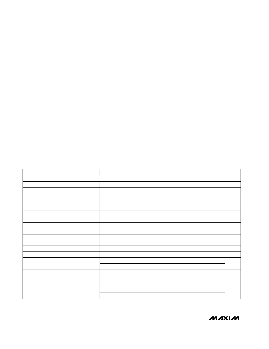
Ordering Information
Idle Mode is a trademark of Maxim Integrated Products, Inc.
Dual Mode is a trademark of Maxim Integrated Products, Inc.
Pin Configurations appear at end of data sheet.
PART
TEMP RANGE
PIN-PACKAGE
MAX1901EAI
-40
∞C to +85∞C
28 SSOP
MAX1901ETJ
-40
∞C to +85∞C
32 Thin QFN 5m m x 5m m
MAX1902EAI
-40
∞C to +85∞C
28 SSOP
MAX1902ETJ
-40
∞C to +85∞C
32 Thin QFN 5m m x 5m m
MAX1904EAI
-40
∞C to +85∞C
28 SSOP
MAX1904ETJ
-40
∞C to +85∞C
32 Thin QFN 5m m x 5m m
MAX1901/MAX1902/MAX1904
500kHz Multi-Output, Low-Noise Power-Supply
Controllers for Notebook Computers
2
_______________________________________________________________________________________
ABSOLUTE MAXIMUM RATINGS
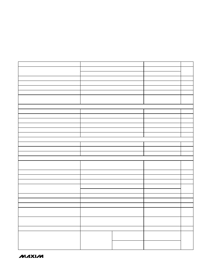
ELECTRICAL CHARACTERISTICS
(V+ = 15V, both PWMs on, SYNC = V
L
, V
L
load = 0, REF load = 0, SKIP = 0, T
A
= 0∞C to +85∞C, unless otherwise noted. Typical
values are at T
A
= +25∞C.)
Stresses beyond those listed under "Absolute Maximum Ratings" may cause permanent damage to the device. These are stress ratings only, and functional
operation of the device at these or any other conditions beyond those indicated in the operational sections of the specifications is not implied. Exposure to
absolute maximum rating conditions for extended periods may affect device reliability.
V+ to GND ..............................................................-0.3V to +36V
PGND to GND.....................................................................±0.3V
V
L
to GND ................................................................-0.3V to +6V
BST3, BST5 to GND ..............................................-0.3V to +36V
CSH3, CSH5 to GND................................................-0.3V to +6V
FB3 to GND ..............................................-0.3V to (CSL3 + 0.3V)
FB5 to GND ...............................................-0.3V to (CSL5 +0.3V)
LX3 to BST3..............................................................-6V to +0.3V
LX5 to BST5..............................................................-6V to +0.3V
REF, SYNC, SEQ, STEER, SKIP,
TIME/ON5, SECFB, RESET to GND ........-0.3V to (V
L
+ 0.3V)
V
DD
to GND. ...........................................................-0.3V to +20V
RUN/ON3, SHDN to GND.............................-0.3V to (V+ + 0.3V)
12OUT to GND ..........................................-0.3V to (V
DD
+ 0.3V)
DL3, DL5 to PGND. .......................................-0.3V to (V
L
+ 0.3V)
DH3 to LX3 ..............................................-0.3V to (BST3 + 0.3V)
DH5 to LX5 ..............................................-0.3V to (BST5 + 0.3V)
V
L
, REF Short to GND ................................................Momentary
12OUT Short to GND..................................................Continuous
REF Current...........................................................+5mA to -1mA
V
L
Current. ........................................................................+50mA
12OUT Current . .............................................................+200mA
V
DD
Shunt Current. ...........................................................+15mA
Continuous Power Dissipation (T
A
= +70∞C)
28-Pin SSOP (derate 9.52mW/∞C above +70∞C) ......762mW
32-Pin Thin QFN (derate 21.3mW/∞C above +70∞C) ..1702mW
Operating Temperature Range ...........................-40∞C to +85∞C
Storage Temperature Range ............................-65∞C to +160∞C
Lead Temperature (soldering, 10s) ................................+300∞C
PARAMETER
CONDITIONS
MIN
TYP
MAX
UNITS
MAIN SMPS CONTROLLERS
Input Voltage Range
4.2
30.0
V
3V Output Voltage in Adjustable Mode
V+ = 4.2V to 30V, CSH3 - CSL3 = 0,
CSL3 tied to FB3
2.42
2.5
2.58
V
3V Output Voltage in Fixed Mode
V+ = 4.2V to 30V, 0 < CSH3 - CSL3
< 80mV, FB3 = 0
3.20
3.39
3.47
V
5V Output Voltage in Adjustable Mode
V+ = 4.2V to 30V, CSH5 - CSL5 = 0,
CSL5 tied to FB5
2.42
2.5
2.58
V
5V Output Voltage in Fixed Mode
V+ = 5.3V to 30V, 0 < CSH5 - CSL5
< 80mV, FB5 = 0
4.85
5.13
5.25
V
Output Voltage Adjust Range
Either SMPS
REF
5.5
V
Adjustable-Mode Threshold Voltage
Dual-mode comparator
0.5
1.1
V
Load Regulation
Either SMPS, 0 < CSH_ - CSL_ < 80mV
-2
%
Line Regulation
Either SMPS, 5.2V < V+ < 30V
0.03
%/V
CSH3 - CSL3 or CSH5 - CSL5
80
100
120
Current-Limit Threshold
SKIP = V
L
or V
DD
< 13V or SECFB < 2.44V
-50
-100
-150
mV
Idle Mode Threshold
SKIP = 0, not tested
10
25
40
mV
Soft-Start Ramp Time
From enable to 95% full current limit with
respect to f
OSC
(Note 1)
512
clks
SYNC = V
L
450
500
550
Oscillator Frequency
SYNC = 0
283
333
383
kHz
MAX1901/MAX1902/MAX1904
500kHz Multi-Output, Low-Noise Power-Supply
Controllers for Notebook Computers
_______________________________________________________________________________________
3
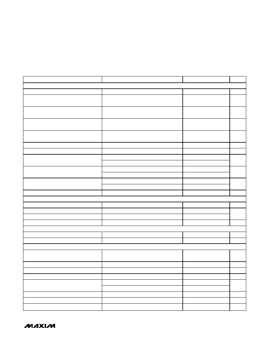
ELECTRICAL CHARACTERISTICS (continued)
(V+ = 15V, both PWMs on, SYNC = V
L
, V
L
load = 0, REF load = 0, SKIP = 0, T
A
= 0∞C to +85∞C, unless otherwise noted. Typical
values are at T
A
= +25∞C.)
PARAMETER
CONDITIONS
MIN
TYP
MAX
UNITS
SYNC = V
L
95
97
Maximum Duty Factor
SYNC = 0 (Note 2)
96.5
98
%
SYNC Input High-Pulse Width
Not tested
200
ns
SYNC Input Low-Pulse Width
Not tested
200
ns
SYNC Rise/Fall Time
Not tested
200
ns
SYNC Input Frequency Range
400
583
kHz
Current-Sense Input Leakage Current
V+ = V
L
= 0,
CSL3 = CSH3 = CSL5 = CSH5 = 5.5V
0.01
10
µA
FLYBACK CONTROLLER
V
DD
Regulation Threshold
Falling edge (Note 3)
13
14
V
SECFB Regulation Threshold
Falling edge (MAX1901/MAX1904)
2.44
2.60
V
DL Pulse Width
V
DD
< 13V or SECFB < 2.44V
0.75
µs
V
DD
Shunt Threshold
Rising edge, hysteresis = 1% (Note 3)
18
20
V
V
DD
Shunt Sink Current
V
DD
= 20V (Note 3)
10
mA
V
DD
Leakage Current
V
DD
= 5V, off mode (Notes 3, 4)
30
µA
12V LINEAR REGULATOR (Note 3)
12OUT Output Voltage
13V < V
DD
< 18V, 0 < I
LOAD
< 120mA
11.65
12.10
12.50
V
12OUT Current Limit
12OUT forced to 11V, V
DD
= 13V
150
mA
Quiescent V
DD
Current
V
DD
= 18V, run mode, no 12OUT load
50
100
µA
INTERNAL REGULATOR AND REFERENCE
V
L
Output Voltage
SHDN = V+, RUN/ON3 = TIME/ON5 = 0,
5.4V < V+ < 30V, 0mA < I
LOAD
< 50mA
4.7
5.1
V
V
L
Undervoltage Lockout-Fault Threshold
Falling edge, hysteresis = 1%
3.5
3.6
3.7
V
V
L
Switchover Threshold
Rising edge of CSL5, hysteresis = 1%
4.2
4.5
4.7
V
REF Output Voltage
No external load (Note 5)
2.45
2.5
2.55
V
0 < I
LOAD
< 50µA
12.5
REF Load Regulation
0 < I
LOAD
< 5mA
100.0
mV
REF Sink Current
10
µA
REF Fault-Lockout Voltage
Falling edge
1.8
2.4
V
V+ Operating Supply Current
V
L
switched over to CSL5, 5V SMPS on
5
50
µA
V+ Standby Supply Current
V+ = 5.5V to 30V, both SMPSs off, includes
current into
SHDN
30
60
µA
V+ Standby Supply Current in Dropout
V+ = 4.2V to 5.5V, both SMPSs off, includes
current into
SHDN
50
200
µA
V+ Shutdown Supply Current
V+ = 4.0V to 30V,
SHDN = 0
4
10
µA
(Note 3)
2.5
4
Quiescent Power Consumption
Both SMPSs enabled,
FB3 = FB5 = 0,
CSL3 = CSH3 = 3.5V,
CSL5 = CSH5 = 5.3V
MAX1901/MAX1904
1.5
4
mW

MAX1901/MAX1902/MAX1904
500kHz Multi-Output, Low-Noise Power-Supply
Controllers for Notebook Computers
4
_______________________________________________________________________________________
ELECTRICAL CHARACTERISTICS (continued)
(V+ = 15V, both PWMs on, SYNC = V
L
, V
L
load = 0, REF load = 0, SKIP = 0, T
A
= 0∞C to +85∞C, unless otherwise noted. Typical
values are at T
A
= +25∞C.)
PARAMETER
CONDITIONS
MIN
TYP
MAX
UNITS
FAULT DETECTION (MAX1901/MAX1902)
Overvoltage Trip Threshold
With respect to unloaded output voltage
4
7
10
%
Overvoltage Fault Propagation Delay
CSL_ driven 2% above overvoltage trip
threshold
1.5
µs
Output Undervoltage Threshold
With respect to unloaded output voltage
60
70
80
%
Output Undervoltage Lockout Time
From each SMPS enabled, with respect to
f
OSC
5,000
6,144
7,000
clks
Thermal-Shutdown Threshold
Typical hysteresis = 10∞C
150
∞C
RESET
RESET Trip Threshold
With respect to unloaded output voltage,
falling edge; typical hysteresis = 1%
-7
-5.5
-4
%
RESET Propagation Delay
Falling edge, CSL_ driven 2% below
RESET
trip threshold
1.5
µs
RESET Delay Time
With respect to f
OSC
27,000
32,000
37,000
clks
INPUTS AND OUTPUTS
Feedback-Input Leakage Current
FB3, FB5; SECFB = 2.6V
1
50
nA
Logic Input-Low Voltage
RUN/ON3,
SKIP, TIME/ON5 (SEQ = REF),
SHDN, STEER, SYNC
0.6
V
Logic Input-High Voltage
RUN/ON3,
SKIP, TIME/ON5 (SEQ = REF),
SHDN, STEER, SYNC
2.4
V
Input Leakage Current
RUN/ON3,
SKIP, TIME/ON5 (SEQ = REF),
SHDN, STEER, SYNC, SEQ; V
PIN
= 0V or 3.3V
±1
µA
Logic Output-Low Voltage
RESET, I
SINK
= 4mA
0.4
V
Logic Output-High Current
RESET = 3.5V
1
mA
TIME/ON5 Input Trip Level
SEQ = 0 or V
L
2.4
2.6
V
TIME/ON5 Source Current
TIME/ON5 = 0, SEQ = 0 or V
L
2.5
3
3.5
µA
TIME/ON5 On-Resistance
TIME/ON5; RUN/ON3 = 0, SEQ = 0 or V
L
15
80
Gate-Driver Sink/Source Current
DL3, DH3, DL5, DH5; forced to 2V
1
A
SSOP package
1.5
7
Gate-Driver On-Resistance
High or low (Note 6)
QFN package
1.5
8
MAX1901/MAX1902/MAX1904
500kHz Multi-Output, Low-Noise Power-Supply
Controllers for Notebook Computers
_______________________________________________________________________________________
5
ELECTRICAL CHARACTERISTICS
(V+ = 15V, both PWMs on, SYNC = V
L
, V
L
load = 0, REF load = 0, SKIP = 0, T
A
= -40∞C to +85∞C, unless otherwise noted.) (Note 7)
PARAMETER
CONDITIONS
MIN
TYP
MAX
UNITS
MAIN SMPS CONTROLLERS
Input Voltage Range
4.2
30.0
V
3V Output Voltage in Adjustable Mode
V+ = 4.2V to 30V, CSH3 - CSL3 = 0,
CSL3 tied to FB3
2.42
2.58
V
3V Output Voltage in Fixed Mode
V+ = 4.2V to 30V, 0 < CSH3 - CSL3
< 80mV, FB3 = 0
3.20
3.47
V
5V Output Voltage in Adjustable Mode
V+ = 4.2V to 30V, CSH5 - CSL5 = 0,
CSL5 tied to FB5
2.42
2.58
V
5V Output Voltage in Fixed Mode
V+ = 5.3V to 30V, 0 < CSH5 - CSL5
< 80mV, FB5 = 0
4.85
5.25
V
Output Voltage Adjust Range
Either SMPS
REF
5.5
V
Adjustable-Mode Threshold Voltage
Dual-mode comparator
0.5
1.1
V
CSH3 - CSL3 or CSH5 - CSL5
80
120
Current-Limit Threshold
SKIP = V
L
or V
DD
< 13V or SECFB < 2.44V
-50
-150
mV
SYNC = V
L
450
550
Oscillator Frequency
SYNC = 0
283
383
kHz
SYNC = V
L
95
Maximum Duty Factor
SYNC = 0 (Note 2)
97
%
SYNC Input Frequency Range
400
583
kHz
FLYBACK CONTROLLER
V
DD
Regulation Threshold
Falling edge (Note 3)
13
14
V
SECFB Regulation Threshold
Falling edge (MAX1901/MAX1904)
2.44
2.60
V
DD
Shunt Threshold
Rising edge, hysteresis = 1% (Note 3)
18
20
V
V
V
DD
Shunt Sink Current
V
DD
= 20V (Note 3)
10
mA
12V LINEAR REGULATOR (Note 3)
12OUT Output Voltage
13V < V
DD
< 18V, 0mA < I
LOAD
< 100mA
11.65
12.50
V
Quiescent V
DD
Current
V
DD
= 18V, run mode, no 12OUT load
100
µA
INTERNAL REGULATOR AND REFERENCE
V
L
Output Voltage
SHDN = V+, RUN/ON3 = TIME/ON5 = 0,
5.4V < V+ < 30V, 0 < I
LOAD
< 50mA
4.7
5.1
V
V
L
Undervoltage Lockout-Fault Threshold
Falling edge, hysteresis = 1%
3.5
3.7
V
V
L
Switchover Threshold
Rising edge of CSL5, hysteresis = 1%
4.2
4.7
V
REF Output Voltage
No external load (Note 5)
2.45
2.55
V
0 < I
LOAD
< 50µA
12.5
REF Load Regulation
0 < I
LOAD
< 5mA
100.0
mV
REF Sink Current
10
µA
REF Fault Lockout Voltage
Falling edge
1.8
2.4
V
V+ Operating Supply Current
V
L
switched over to CSL5, 5V SMPS on
50
µA