 | –≠–ª–µ–∫—Ç—Ä–æ–Ω–Ω—ã–π –∫–æ–º–ø–æ–Ω–µ–Ω—Ç: MAX1501 | –°–∫–∞—á–∞—Ç—å:  PDF PDF  ZIP ZIP |

General Description
The MAX1501 intelligent, constant-current, constant-
voltage (CCCV), temperature-regulated battery charger
charges a single lithium-ion (Li+) cell or three-cell
NiMH/NiCd batteries. The device integrates the current-
sense resistor, PMOS pass element, and thermal-
regulation circuitry, while eliminating the reverse-
blocking Schottky diode to create the simplest charging
solution for hand-held equipment.
The MAX1501 functions as a stand-alone charger to
control the charging sequence from the prequalification
state through fast charge, top-off, and charge termination
for single-cell Li+ or three-cell NiMH/NiCd batteries.
Alternatively, the MAX1501 collaborates with a host
microprocessor to determine the best charging algorithm.
Proprietary thermal-regulation circuitry limits the die
temperature when fast charging or while exposed to high
ambient temperatures, allowing maximum charging
current without damaging the charger. The MAX1501
continually supplies a regulated output voltage under
no-battery conditions, allowing battery changing.
The device achieves high flexibility by providing an
adjustable fast-charge current, top-off current, safety
timer, and thermal-regulation setpoint. Other features
include input power detection (
ACOK) and input under-/
overvoltage protection. The MAX1501 provides active-
low control inputs.
The MAX1501 accepts a 4.5V to 13V supply, but
disables charging when the input voltage exceeds
6.5V, preventing excessive power dissipation. The
MAX1501 operates over the extended temperature
range (-40∞C to +85∞C) and is available in a compact
16-pin thermally enhanced 5mm x 5mm thin QFN
package with 0.8mm profile.
Applications
Cellular and Cordless Phones
PDAs
Digital Cameras and MP3 Players
USB Appliances
Charging Cradles and Docks
BluetoothTM Equipment
Features
o Stand-Alone or Microprocessor-Controlled (µP)
Linear 1-Cell Li+ or 3-Cell NiMH/NiCd Battery
Charger
o No FET, Reverse-Blocking Diode, or Current-
Sense Resistor Required
o 1.4A (max) Programmable Fast-Charge Current
o +95∞C, +115∞C, and +135∞C Proprietary
Programmable Die Temperature Regulation
Control
o 4.5V to 13V Input Voltage Range with Input
Overvoltage (OVLO) Protection Above 6.5V
o Programmable Top-Off Current Threshold: 10%,
20%, or 30% of the Fast-Charge Current
o Charge-Current Monitor for Fuel Gauging
o Programmable Safety Timer (3, 4.5, or 6 hours)
o Input Power Detection Output (ACOK) and Charge
Enable Input (
CHGEN)
o Automatic Recharge
o Digital Soft-Start Limits Inrush Current
o Charge Status Outputs for LEDs or µP Interface
MAX1501
Highly Integrated, Linear Battery Charger with
Thermal Regulation for Portable Applications
________________________________________________________________ Maxim Integrated Products
1
Ordering Information
19-2800; Rev 0; 4/03
For pricing, delivery, and ordering information, please contact Maxim/Dallas Direct! at
1-888-629-4642, or visit Maxim's website at www.maxim-ic.com.
PART
TEMP RANGE
PIN-PACKAGE
MAX1501ETE
-40∞C to +85∞C
16 Thin QFN
Pin Configuration appears at end of data sheet.
MAX1501
1
µF
INPUT
4.5V TO 13V
2.8k
IN
INP
TEMP
TMAX
SETI
GND
GLED
RLED
10
µF
4.2V 1-CELL Li+
R
PULLUP
V
LOGIC
(
5.5V)
BATT
FULLI
VL
SELV
MODE
CHGEN
ACOK
Typical Operating Circuit
Bluetooth is a trademark of Ericsson.

MAX1501
Highly Integrated, Linear Battery Charger with
Thermal Regulation for Portable Applications
2
_______________________________________________________________________________________
ABSOLUTE MAXIMUM RATINGS
ELECTRICAL CHARACTERISTICS
(V
IN
= V
INP
= 5V, V
BATT
= 3.5V,
ACOK = GLED = RLED = TEMP = TMAX = FULLI = open, CHGEN = MODE = GND, R
SETI
= 2.8k
,
C
IN
= 1µF, C
BATT
= 10µF, T
A
= 0∞C to +85∞C, unless otherwise noted. Typical values are at T
A
= +25
∞C.)
Stresses beyond those listed under "Absolute Maximum Ratings" may cause permanent damage to the device. These are stress ratings only, and functional
operation of the device at these or any other conditions beyond those indicated in the operational sections of the specifications is not implied. Exposure to
absolute maximum rating conditions for extended periods may affect device reliability.
IN, INP,
RLED, GLED to GND ................................-0.3V to +14V
IN to INP ................................................................-0.3V to +0.3V
VL, BATT, SETI,
ACOK, MODE, CHGEN, SELV,
FULLI, TMAX, TEMP to GND ................................-0.3V to +6V
VL to IN...................................................................-14V to +0.3V
Continuous Power Dissipation (T
A
= +70
∞C)
16-Pin 5mm
5mm Thin QFN
(derate 21.3mW/
∞C above +70∞C).............................1702mW
Operating Temperature Range ...........................-40
∞C to +85∞C
Junction Temperature ......................................................+150
∞C
Storage Temperature Range .............................-65
∞C to +150∞C
Lead Temperature (soldering, 10s) .................................+300
∞C
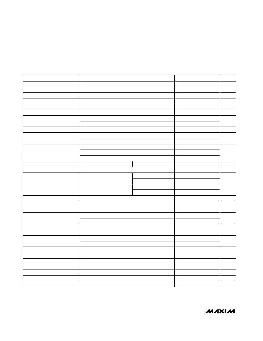
PARAMETER
CONDITIONS
MIN
TYP
MAX
UNITS
IN, INP Input Voltage
0
13
V
IN, INP Input Operating Range
4.50
6.25
V
VL Output Voltage
4.5V
V
IN
6.25V, I
VL
< 250µA
2.7
3
3.3
V
V
IN
- V
BATT
, rising
40
70
100
V
IN
- V
BATT
, falling
30
55
85
ACOK Trip Point
V
IN
- V
BATT
, hysteresis
15
mV
ACOK Sink Current
4.5V
V
IN
6.25V, V
ACOK
= 0.6V
75
µA
V
IN
rising
4.05
4.125
4.20
V
IN
falling
3.9
4.025
4.1
V
Undervoltage Lockout Trip Point
Hysteresis
100
mV
Overvoltage Lockout Trip Point
V
IN
rising
6.25
6.50
6.75
V
Li+, NiMH/NiCd, and no-battery modes
5
8
Disable mode
1.5
3
IN Input Current
Off mode (V
IN
= 4V)
0.25
mA
V
BATT
= 4.3V
45
80
V
IN
= 0
3
10
BATT Input Current
Disable mode
2
6
µA
Leakage into Battery
V
IN
= V
INP
= 13V, V
BATT
= 0
Disable mode
5
µA
RMS Charge Current
1.4
A
SELV = VL
4.166
4.2
4.234
Li+ mode
SELV = GND
4.067
4.1
4.133
SELV = VL,
V
IN
= V
INP
= 6V
4.85
4.95
5.05
Battery Regulation Voltage
NiMH/NiCd mode
SELV = GND
4.4
4.5
4.6
V
Output Regulation Voltage
No-battery mode
3.700
4.0
4.234
V
BATT Precharge Threshold
Voltage
BATT rising
2.675
2.8
2.925
V
R
SETI
= 2.8k
460
500
540
Fast-Charge Current-Loop
System Accuracy
R
SETI
= 1.75 k
736
800
864
mA

MAX1501
Highly Integrated, Linear Battery Charger with
Thermal Regulation for Portable Applications
_______________________________________________________________________________________
3
ELECTRICAL CHARACTERISTICS (continued)
(V
IN
= V
INP
= 5V, V
BATT
= 3.5V,
ACOK = GLED = RLED = TEMP = TMAX = FULLI = open, CHGEN = MODE = GND, R
SETI
= 2.8k
,
C
IN
= 1µF, C
BATT
= 10µF, T
A
= 0∞C to +85∞C, unless otherwise noted. Typical values are at T
A
= +25
∞C.)
PARAMETER
CONDITIONS
MIN
TYP
MAX
UNITS
Precharge Current System
Accuracy
% of fast-charge current, V
BATT
= 2V
5
10
15
%
TEMP = GND
95
TEMP = open
115
Die Temperature Regulation
Setpoint (Note 1)
TEMP = VL
135
o
C
I
BATT
to I
SETI
, precharge mode, V
BATT
= 2V
0.70
1
1.30
Current-Sense Amplifier Gain
I
BATT
to I
SETI
, fast-charge mode
0.95
1
1.05
mA/A
Internal Current-Sense
Resistance
84
m
Regulator Dropout Voltage
V
IN
- V
BATT
, NiMH/NiCd mode, V
BATT
= 4.3V,
I
BATT
= 425mA
190
350
mV
Logic Input Low Voltage
CHGEN, MODE, 4.5V
V
IN
6.25V
0.52
V
Logic Input High Voltage
CHGEN, MODE, 4.5V
V
IN
6.25V
1.25
V
Internal Pulldown Resistance
CHGEN, MODE
100
175
400
k
Internal Pullup Resistance
SELV
100
175
400
k
Internal Bias Resistance
FULLI, TEMP, TMAX
50
90
200
k
Internal Bias Voltage
FULLI, TEMP, TMAX
V
VL
/2
V
RLED Output Low Current
V
RLED
= 1V
7
10
18
mA
GLED Output Low Current
V
GLED
= 1V
14
20
34
mA
GLED, RLED Output High
Leakage Current
V
GLED
= V
RLED
= V
IN
= V
INP
= 13V
0.1
1
µA
FULLI = GND
5
10
15
FULLI = VL
15
20
25
Full-Battery Detection Current
Threshold
% of fast-charge
current
FULLI = open
25
30
35
%
SELV = VL
3.9
4.0
4.1
Li+ mode
SELV = GND
3.8
3.9
4.0
V
BATT
Restart Threshold
NiMH/NiCd mode
3.9
4.0
4.1
V
Charge-Timer Accuracy
-10
+10
%
TMAX = GND
3
TMAX = open
4.5
Charge-Timer Duration
TMAX = VL
6
hrs
MAX1501
Highly Integrated, Linear Battery Charger with
Thermal Regulation for Portable Applications
4
_______________________________________________________________________________________
ELECTRICAL CHARACTERISTICS
(V
IN
= V
INP
= 5V, V
BATT
= 3.5V,
ACOK = GLED = RLED = TEMP = TMAX = FULLI = open, CHGEN = MODE = GND, R
SETI
= 2.8k
,
C
IN
= 1µF, C
BATT
= 10µF, T
A
= -40∞C to +85∞C, unless otherwise noted. Typical values are at T
A
= +25
∞C.) (Note 2)
PARAMETER
CONDITIONS
MIN
TYP
MAX
UNITS
IN, INP Input Voltage
0
13
V
IN, INP Input Operating Range
4.50
6.25
V
VL Output Voltage
4.5V
V
IN
6.25V, I
VL
< 250µA
2.7
3.3
V
V
IN
- V
BATT
, rising
40
100
ACOK Trip Point
V
IN
- V
BATT
, falling
30
85
mV
ACOK Sink Current
4.5V
V
IN
6.25V, V
ACOK
= 0.6V
75
µA
V
IN
rising
4.00
4.25
Undervoltage Lockout Trip Point
V
IN
falling
3.90
4.15
V
Overvoltage Lockout Trip Point
6.25
6.75
V
Li+, NiMH/NiCd, and no-battery modes
8
IN Input Current
Disable mode
3
mA
V
BATT
= 4.3V
80
V
IN
= 0
10
BATT Input Current
Disable mode
6
µA
Leakage into Battery
V
IN
= V
INP
= 13V, V
BATT
= 0
Disable mode
5
µA
RMS Charge Current
1.4
A
SELV = VL
4.148
4.252
Li+ mode
SELV = GND
4.05
4.15
SELV = VL
4.85
5.05
Battery Regulation Voltage
NiMH/NiCd mode
SELV = GND
4.4
4.6
V
Output Regulation Voltage
No-battery mode
3.700
4.234
V
BATT Precharge Threshold
Voltage
BATT rising
2.675
2.925
V
R
SETI
= 2.8k
460
540
Fast-Charge Current-Loop
System Accuracy
R
SETI
= 1.75k
736
864
mA
Precharge Current System
Accuracy
% of fast-charge current, V
BATT
= 2V
5
15
%
I
BATT
to I
SETI
, precharge mode, V
BATT
= 2V
0.60
1.40
Current-Sense Amplifier Gain
I
BATT
to I
SETI
, fast-charge mode
0.93
1.07
mA/A
Regulator Dropout Voltage
V
IN
- V
BATT
, NiMH/NiCd mode, V
BATT
= 4.3V,
I
BATT
= 425mA
350
mV
Logic Input Low Voltage
CHGEN, MODE, 4.5V < V
IN
< 6.25V
0.52
V
Logic Input High Voltage
CHGEN, MODE, 4.5V < V
IN
< 6.25V
1.3
V
Internal Pulldown Resistance
CHGEN, MODE
100
400
k
Internal Pullup Resistance
SELV
100
400
k
Internal Bias Resistance
FULLI, TEMP, TMAX
50
200
k

MAX1501
Highly Integrated, Linear Battery Charger with
Thermal Regulation for Portable Applications
_______________________________________________________________________________________
5
Note 1: Temperature regulation setpoint variation is typically ±9∞C.
Note 2: Specifications to T
A
= -40∞C are guaranteed by design, not production tested.
ELECTRICAL CHARACTERISTICS (continued)
(V
IN
= V
INP
= 5V, V
BATT
= 3.5V,
ACOK = GLED = RLED = TEMP = TMAX = FULLI = open, CHGEN = MODE = GND, R
SETI
= 2.8k
,
C
IN
= 1µF, C
BATT
= 10µF, T
A
= -40∞C to +85∞C, unless otherwise noted. Typical values are at T
A
= +25
∞C.) (Note 2)
PARAMETER
CONDITIONS
MIN
TYP
MAX
UNITS
RLED Output Low Current
V
RLED
= 1V
7
18
mA
GLED Output Low Current
V
GLED
= 1V
14
34
mA
GLED, RLED Output High
Leakage Current
V
GLED
= V
RLED
= V
IN
= V
INP
= 13V
1
µA
Charge-Timer Accuracy
-10
+10
%
Typical Operating Characteristics
(V
IN
= V
INP
= 5V,
ACOK = RLED = GLED = TEMP = TMAX = FULLI = open, C
BATT
= 10µF, C
IN
= 1µF, T
A
= +25
∞C, unless otherwise noted.)
SUPPLY CURRENT vs. INPUT VOLTAGE
MAX1501 toc01
INPUT VOLTAGE (V)
SUPPLY CURRENT (mA)
12
11
9 10
3
4
5
6
7
8
1
2
0.5
1.0
1.5
2.0
2.5
3.0
3.5
4.0
4.5
5.0
0
0
13
Li+ MODE OR
NiMH/NiCd MODE,
SELV = VL, I
BATT
= 0
DISABLE-MODE SUPPLY CURRENT
vs. INPUT VOLTAGE
MAX1501 toc02
INPUT VOLTAGE (V)
DISABLE-MODE SUPPLY CURRENT (mA)
12
11
9 10
3
4
5
6
7
8
1
2
0.2
0.4
0.6
0.8
1.0
1.2
1.4
1.6
1.8
2.0
0
0
13
CHARGE CURRENT
vs. BATTERY VOLTAGE
MAX1501 toc03
BATTERY VOLTAGE (V)
CHARGE CURRENT (mA)
4.0
3.5
2.5 3.0
1.0 1.5 2.0
0.5
50
100
150
200
250
300
350
400
450
500
550
600
0
0
4.5
Li+ MODE, R
SETI
= 2.7k
,
V
IN
= 5V, SELV = VL
CHARGE CURRENT
vs. BATTERY VOLTAGE
MAX1501 toc04
BATTERY VOLTAGE (V)
CHARGE CURRENT (mA)
4.5
4.0
3.0 3.5
1.0 1.5 2.0 2.5
0.5
50
100
150
200
250
300
350
400
450
500
550
600
0
0
5.0
NiMH/NiCd, R
SETI
= 2.7k
,
V
IN
= 5.5V, SELV = VL
CHARGE CURRENT
vs. INPUT VOLTAGE
MAX1501 toc05
INPUT VOLTAGE (V)
CHARGE CURRENT (mA)
12
11
9 10
3
4
5
6
7
8
1
2
50
100
150
200
250
300
350
400
450
500
550
600
0
0
13
Li+ MODE,
SELV = VL,
R
SETI
= 2.7k
CHARGE CURRENT
vs. INPUT-VOLTAGE HEADROOM
MAX1501 toc06
V
IN
- V
BATT
(V)
CHARGE CURRENT (mA)
1.8
1.6
1.2 1.4
0.4 0.6 0.8 1.0
0.2
50
100
150
200
250
300
350
400
450
500
550
600
0
0
2.0
NiMH/NiCd MODE, SELV = GND,
R
SETI
= 2.7k
, V
BATT
= 4.3V