General Description
The MAX1200/MAX1201/MAX1205 evaluation kits (EV
kits) are assembled and tested PC boards that include
the basic components necessary to drive either the 16-bit
MAX1200 or 14-bit MAX1201/MAX1205 analog-to-digital
converters (ADCs). Connectors for power supplies, ana-
log inputs, and digital outputs simplify connections to the
device. The PC board layouts are optimized for best
dynamic performance. Each EV kit is fully assembled and
tested, and includes a MAX1200, MAX1201, or MAX1205
(as requested) that is soldered and ready to test.
Features
o
Accepts Single-Ended or Differential Inputs
o
Accepts Sine or Square Clock Input
o
Proven PC Board Layout
o
Convenient Test Points Provided On-Board
o
Fully Assembled and Tested Surface-Mount
Board
Evaluate: MAX1200/MAX1201/MAX1205
MAX1200/MAX1201/MAX1205 Evaluation Kits
________________________________________________________________
Maxim Integrated Products
1
19-4795; Rev 1; 11/98
Component List
PART
TEMP. RANGE
IC PACKAGE
For free samples & the latest literature: http://www.maxim-ic.com, or phone 1-800-998-8800.
For small orders, phone 1-800-835-8769.
Ordering Information
10
, 5% resistors
3
R5, R6, R43
100
, 5% resistor
1
R4
5k
, 5% resistors
3
R2, R3, R16
10k
potentiometer
1
R1
Ferrite beads
Panasonic ECE-CL3216U
7
FB1≠FB5
390pF, 25V ceramic capacitor
1
C51
DESIGNATION
100pF, 25V ceramic capacitors
2
C38, C39
0.47ĶF, 25V ceramic capacitors
2
C19, C24
10ĶF, 16V tantalum capacitors
AVX TAJB106K006
2
C13, C18
0.1ĶF, 25V ceramic capacitors
31
C2, C4, C6, C8,
C9, C10, C12,
C14≠C17, C20,
C21, C22, C25,
C26, C30, C31,
C35, C36, C37,
C40, C41, C42,
C44, C45, C48,
C49, C50, C57,
C58
22ĶF, 16V tantalum capacitors
AVX TAJD226K016
5
C1, C3, C5,
C7, C11
DESCRIPTION
QTY
MAX1200
EVKIT-MQFP
0įC to +70įC
44 MQFP
33
, 5% resistors
4
R7, R30,
R35, R42
1.21k
, 1% resistor
1
R27
10k
, 5% resistors
3
R17, R19, R21
3-pin headers
2
JU1, JU2
SMA connectors
8
CLK_SINE,
CLK_SQ, IN,
IN+AP, IN-AP,
IN_XFR, REF+,
REF-
976
, 1% resistors
8
R28, R29, R31≠
R34, R36, R37
DESIGNATION
DESCRIPTION
QTY
2 x 20 header
1
J3
2-pin headers
7
J1, J2, J5, J7,
J10, JU3, JU4
74HC541 three-state buffers
3
U1, U2, U3
Momentary pushbutton switch
1
SW1
Test points
7
+5V_A, +5V_D,
+5V_DR, +7V,
-3V, AGND,
DGND
Shunts
7
None
200
, 1% resistor
1
R39
54.9
, 1% resistor
1
R38
Component List continued on next page.
1k
, 5% resistors
6
R14, R15,
R23≠R26
Panasonic AEM-MLB-805 G601 P
2
FB6, FB7
MAX1201
EVKIT-MQFP
0įC to +70įC
44 MQFP
MAX1205
EVKIT-MQFP
0įC to +70įC
44 MQFP

Evaluate: MAX1200/MAX1201/MAX1205
MAX1200/MAX1201/MAX1205 Evaluation Kits
2
_______________________________________________________________________________________
_________________________Quick Start
Recommended Equipment
You will need the following equipment before you
begin:
∑
A triple-output power supply (-3V, +5V, and +7V)
∑
A signal source, such as an HP8662A RF signal gen-
erator
∑
Two stable precision voltage references
∑
A low-phase-noise clock source, such as an
HP8662A pulse generator, filtered by a 10MHz low-
pass filter (Mini Circuits SLP-10.7).
∑
A logic analyzer, such as an HP16500B, to collect
the data
The EV kit is shipped fully assembled and tested.
Follow these steps to verify board operation.
Do not
turn on the power supply until all connections are
completed.
1) Connect the power supplies to the -3V, +7V, +5V,
AGND, and DGND pads. For best results, use sepa-
rate analog and digital leads, connecting AGND to
DGND close to the power supply's common termi-
nal.
2) Connect a signal source to the IN or IN+AP/IN-AP
inputs. If using differential inputs, common-mode
voltage should be halfway between REF+ and REF-.
3) Connect the voltage references to the REF+ and
REF- inputs.
4) Connect a sine-wave clock source to the CLK_SINE
input. If using a square wave instead of a sine wave,
connect it to the CLK_SQ input instead.
5) Turn on the logic analyzer and connect it to header
J3. Configure it to receive data on the rising edge of
the DAV strobe signal.
6) Turn on the EV kit's power supplies.
7) Press momentary switch SW1 to trigger self-calibra-
tion.
8) Turn on the input signal source.
9) Collect data using the logic analyzer.
Hardware Description
The MAX120x EV kit accepts a differential input signal
between IN+AP and IN-AP, or it can accept a single-
ended (i.e., ground-referenced) input signal at IN. The
PC board can also accommodate a Balun transformer
at T1; however, transformer-coupling the input may
degrade signal performance.
U12, the MAX1200, is a 16-bit, 1Msps ADC with parallel
two's complement data outputs. The MAX1201/
MAX1205 are 14-bit versions of the MAX1200.
Data output signals are buffered by U1, U2, and U3
and provided at header J3 for evaluation.
Reference Input
The MAX410 op amps designated as U8 and U9 on the
EV board buffer the REF+ and REF- inputs.
The MAX410 op amp designated as U7 on the EV board
buffers resistor-dividers R2/R1/R3, providing a common-
mode voltage level halfway between REF+ and REF-.
Trim pot R1 adjusts the common-mode voltage.
The op amps have a maximum total supply-voltage rat-
ing of 10V. The supply rails have been set to V
SS
= -3V
and V
CC
= +7V to keep the signals well within the com-
mon-mode range of these op amps.
Balun transformer
Coiltronics CTX03-13675-X330FL97
Rev A (not supplied)
0
T1
PC board
1
None
Maxim MAX410CSA op amps
3
U7, U8, U9
Maxim MAX961EUA comparator
1
U6
Maxim MAX4108ESA op amps
2
U10, U11
Maxim MAX1200CMH, MAX1201CMH,
or MAX1205CMH
1
U12
DESIGNATION
DESCRIPTION
QTY
Component List (continued)
Evaluate: MAX1200/MAX1201/MAX1205
MAX1200/MAX1201/MAX1205 Evaluation Kits
_______________________________________________________________________________________
3
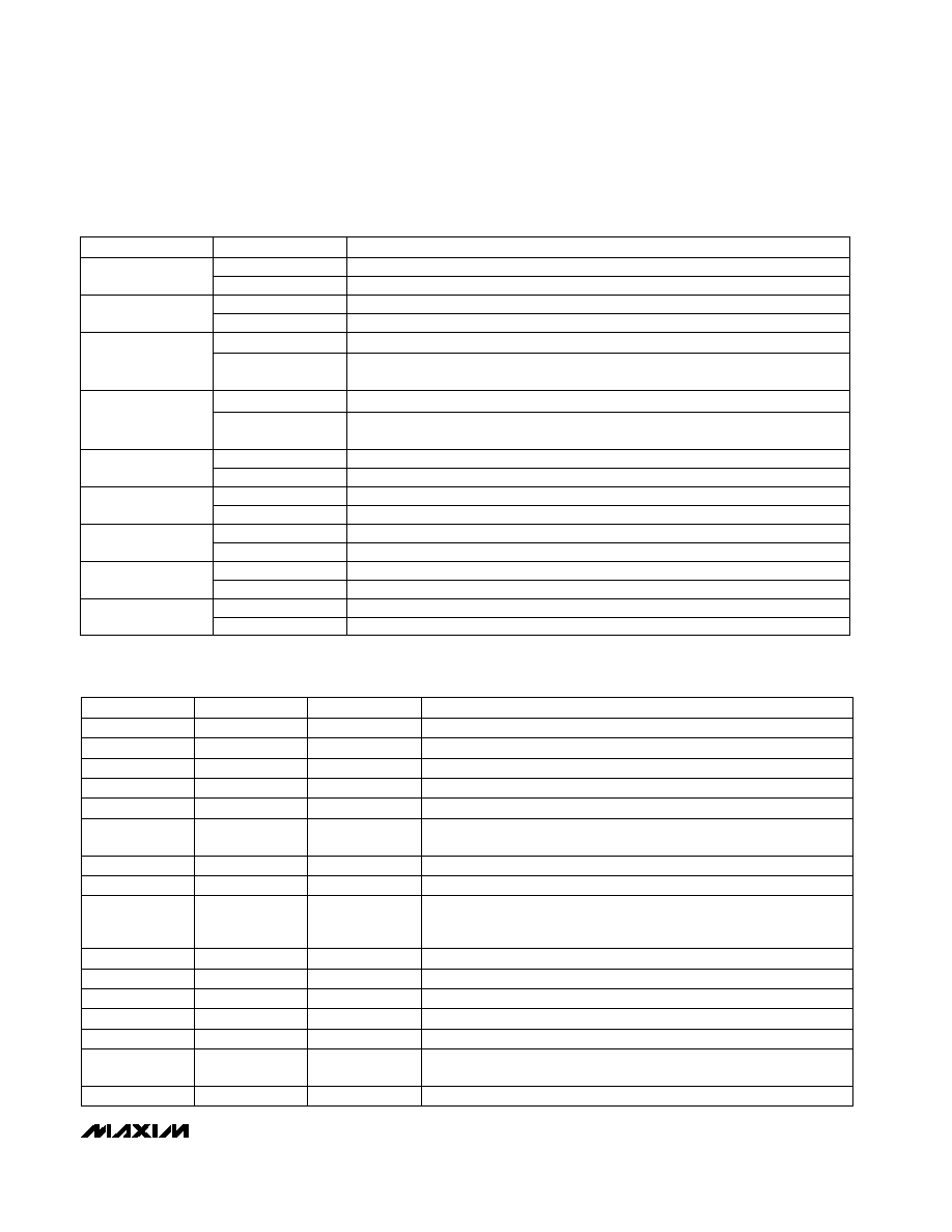
JUMPER
STATE
FUNCTION
1≠2
Apply a single-ended input at the "IN" SMA connector.
JU1
2≠3*
Apply a differential input between the "IN+AP" and "IN-AP" SMA connectors.
Table 1. Jumper Functions
1≠2
Apply a single-ended input at the "IN" SMA connector.
JU2
2≠3*
Apply a differential input between the "IN+AP" and "IN-AP" SMA connectors.
Open*
Normal operation with no balun transformer.
Closed
Install balun transformer T1 and apply an input signal at the "IN_XFR" connector.
Not supported as shipped from the factory.
Open*
Normal operation with no balun transformer.
Closed
Install balun transformer T1 and apply an input signal at the "IN_XFR" connector.
Not supported as shipped from the factory.
Open
14-bit MAX1201/MAX1205
J1
Closed
16-bit MAX1200
Open
14-bit MAX1201/MAX1205
J2
Closed
16-bit MAX1200
Open
Enable remote REF+ force/sense.
J5
Closed
Disable REF+ force/sense.
Open
Enable remote REF- force/sense.
J7
Closed
Disable REF- force/sense.
Open
Apply a square-wave clock at the "CLK_SQ" SMA connector.
J10
Closed*
Apply a sinusoidal clock at the "CLK_SINE" SMA connector.
*
Indicates default jumper state.
JU3
JU4
Table 2. I/O Connectors
LABEL
TYPE
DESCRIPTION
SMA
Reference voltage input, positive connection
REF+
SMA
Reference voltage input, negative connection
REF-
DIRECTION
Input
Input
SMA
Differential signal input, positive connection
IN+AP
SMA
Differential signal input, negative connection
Input
Input
IN-AP
SMA
Single-ended signal input
IN
SMA
Signal input to optional balun transformer T1.
Not supported as shipped
from the factory.
Input
Input
IN_XFR
SMA
Clock input, sine wave
CLK_SINE
SMA
Clock input, square wave
Input
Input
CLK_SQ
2 x 20
Header
Two's complement data outputs:
MAX1200: D0≠D15, D15 = MSB;
MAX1201/MAX1205: D0≠D13, D13 = MSB.
J3
Solder Pad
Negative power-supply rail for op amps
Output
Power Input
-3V
Solder Pad
Positive power-supply rail for op amps
+7V
Power Input
Solder Pad
Analog ground return
AGND
Solder Pad
Digital ground return
Power Input
Power Input
DGND
Solder Pad
Positive power supply for digital outputs DOR, D0≠D15. The +5V_DR
voltage must not exceed +5V_D.
+5V_DR
Solder Pad
Positive power supply for digital circuitry
Power Input
Power Input
+5V_D
Solder Pad
Positive power supply for analog circuitry
+5V_A
Power Input

Evaluate: MAX1200/MAX1201/MAX1205
MAX1200/MAX1201/MAX1205 Evaluation Kits
4
_______________________________________________________________________________________
-3V
C31
IN-AP
IN+AP
IN
IN_XFR
U10
MAX4108
4
R30
33
NOTE: ALL CAPACITOR VALUES ARE 0.1
Ķ
F,
UNLESS OTHERWISE NOTED.
C15
+7V
7
2
3
-3V
C26
U11
4
C25
+7V
7
2
3
5
R36
976
1%
R38
54.9
1%
R28
976
1%
R32
976
1%
R31
976
1%
R37
976
1%
R37
976
1%
R35
33
R33
976
1%
R34
976
1%
R29
976
1%
6
6
R39
200
1%
R27
1.21k
1%
R7
33
R42
33
C51
390pF
INPF
INNF
CMI
from U7
CMI
FROM U7
C36
4
3
5
C37
5V_A
8
7
1
2
R14
1k
R16
5k
R15
1k
R43
10
6
5V_A
2
CLK_SINE
12
9
7
CM
T1
JU4
JU1
JU2
JU3
3 2 1
3 2 1
C35
CLK_SQ
J10
Q
Q
CLK
U6
MAX4108
MAX961
Figure 1. MAX1200/MAX1201/MAX1205 EV Kits Schematic

Evaluate: MAX1200/MAX1201/MAX1205
MAX1200/MAX1201/MAX1205 Evaluation Kits
_______________________________________________________________________________________
5
+7V
+7V
FB2
FB4
FB5
FB1
FB3
C3
22
Ķ
F
C1
22
Ķ
F
C7
22
Ķ
F
C5
22
Ķ
F
C48
C6
C11
22
Ķ
F
C4
C10
C12
AGND
-3V
-3V
+5V_A
5V_A
+5V_DR
+5V_D
5V_D
5V_DR
DGND
DGND
DGND
DGND
DGND
-3V
C21
C22
C49
R23
1k
REF-
REF+
4
R6
10
C24
0.47
Ķ
F
C30
+7V
7
2
3
-3V
C16
4
C20
+7V
7
2
3
-3V
C2
4
C9
+7V
7
2
3
R26
1k
R3
5k
R2
5k
R1
10k
R5
10
C17
R25
1k
C19
0.47
Ķ
F
C50
R24
1k
6
6
6
R4
100
C14
C13
10
Ķ
F
C18
10
Ķ
F
J5
RFPS
RFPF
CMI
RFNS
RFNF
CM
J7
U8
MAX410
U7
MAX410
U9
MAX410
NOTE: ALL CAPACITOR VALUES ARE 0.1
Ķ
F, 25V,
UNLESS OTHERWISE NOTED.
Figure 1. MAX1200/MAX1201/MAX1205 EV Kits Schematic (continued)