 | –≠–ª–µ–∫—Ç—Ä–æ–Ω–Ω—ã–π –∫–æ–º–ø–æ–Ω–µ–Ω—Ç: AM05-0006 | –°–∫–∞—á–∞—Ç—å:  PDF PDF  ZIP ZIP |

Features
n
Gain: 10.1 dB Nominal
n
IP3 of +43 dBm Typical
n
Land Grid Array (LGA) Package
n
Compression point of +27 dBm Typical
n
50 ohm impedance
n
Test boards are available
n
Tape and Reel Packaging Available
Description
M/A-COM's AM05-0006 is a coupler feedback amplifier
with high intercept and compression points. This device is
in a ceramic land grid array package. This package is
designed for standard surface mount pick and place. Due
to the ceramic package the thermal rise minimized. The
ground plane on the PC board should be configured to
remove heat from under the package. AM05-0006 is
ideally suited for use where a high intercept commercial
amplifier is required at a low cost.
High Intercept Amplifier,
15 - 100 MHz
AM05
-
0006
LGA-1
Electrical Specifications: T
A
= 25∞C
Parameter
Test Conditions
Frequency
Units
Min.
Typ.
Max.
Gain
--
50 MHz
dB
9.6
10.1
10.6
Gain Flatness
--
15 - 100 MHz
dB
--
± 0.2
± 0.4
VSWR
--
15 - 100 MHz
Ratio
--
1.4:1
1.8:1
1 dB Compression
Output Power
15 - 100 MHz
dBm
23
27
--
Output IP
2
Two-tone inputs up to +10 dBm
15 - 100 MHz
dBm
55
65
--
Output IP
3
Two-tone inputs up to +10 dBm
15 - 100 MHz
dBm
40
46
--
Noise Figure
--
15 - 100 MHz
dB
--
3.0
5.0
Reverse Transmission
--
15 - 100 MHz
dB
--
-14
-13
+V
--
--
V
11.4
12.0
12.6
Ibias
1.1W Typical
--
mA
--
88
120
V 2.00
High Intercept Amplifier, 15 - 100 MHz
AM05-0006
Specifications subject to change without notice.
n
North America: Tel. (800) 366-2266
n
Asia/Pacific: Tel.+81-44-844-8296, Fax +81-44-844-8298
n
Europe: Tel. +44 (1344) 869 595, Fax+44 (1344) 300 020
Visit www.macom.com for additional data sheets and product information.
V 2.00
2
Absolute Maximum Ratings
1
1. Operation of this device above any one of these
parameters may cause permanent damage.
Parameter
Absolute Maximum
Max Input Power
+15 dBm
Vbias
-0.5 to +14.0 V
Operating Temperature
-40∞C to +85∞C
Storage Temperature
-65∞C to +125∞C
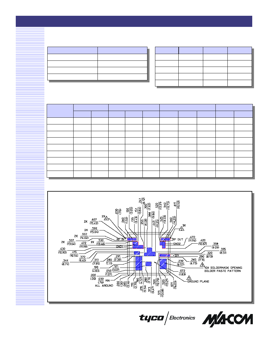
Pin Configuration
Pin #
Function
Pin #
Function
1
RF IN
6
V
bias
2
GND 1
7
GND 2
3
GND
8
RF OUT
4
GND
9
GND
5
GND
10
GND
Recommended Board Layout
S-Parameter Data
S11
S21
S12
S22
MAG
ANG
dB
MAG
ANG
dB
MAG
ANG
MAG
ANG
5
0.0928
-30
9.63
3.03
-176
-14.28
0.19
175
0.1105
44
20
0.0576
-32
9.98
3.16
170
-14.02
0.20
170
0.0513
-20
35
0.0384
-22
10.13
3.21
158
-13.95
0.20
161
0.0453
-22
50
0.0323
-3
10.21
3.24
146
-14.05
0.20
151
0.0582
-21
65
0.0355
26
10.29
3.27
136
-14.27
0.19
141
0.0792
-27
80
0.0471
45
10.41
3.31
124
-14.61
0.19
133
0.1042
-37
95
0.0618
50
10.53
3.36
113
-15.03
0.18
124
0.1288
-49
110
0.0778
51
10.71
3.43
102
-15.54
0.17
115
0.1496
-61
125
0.0936
49
10.95
3.53
91
-16.19
0.16
107
0.1639
-74
Frequency
(MHz)
High Intercept Amplifier, 15 - 100 MHz
AM05-0006
Specifications subject to change without notice.
n
North America: Tel. (800) 366-2266
n
Asia/Pacific: Tel.+81-44-844-8296, Fax +81-44-844-8298
n
Europe: Tel. +44 (1344) 869 595, Fax+44 (1344) 300 020
Visit www.macom.com for additional data sheets and product information.
V 2.00
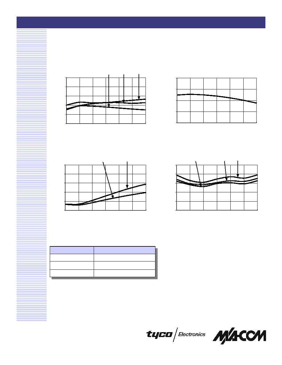
Typical Performance Curves
Reverse Isolation vs. Frequency
Insertion Loss vs. Frequency
VSWR vs. Frequency
3
Noise Figure vs. Frequency
Ordering Information
Part Number
Package
AM05-0006
Bulk Packaging
AM05-0006TR
Tape and Reel (1K Reel)
AM05-0006-TB
Device provided on Test Board
-19
-17
-15
-13
-11
15
30
45
60
75
90
105
Frequency (MHz)
Reverse Isolation (dB)
9.0
9.5
10.0
10.5
11.0
11.5
15
30
45
60
75
90
105
Frequency (MHz)
Gain (dB)
+85∞C
- 40∞C
+25∞C
+85∞C
-40∞C
1.00
1.20
1.40
1.60
1.80
2.00
15
30
45
60
75
90
105
Frequency (MHz)
VSWR
RF IN
RF OUT
0
1
2
3
4
5
15
30
45
60
75
90
105
Frequency (MHz)
Noise Figure (dB)
-40∞C
+25∞C
+85∞C