1 - 2
© 2002 IXYS All rights reserved
204
Features
∑ NPT
3
IGBT
- low saturation voltage
- positive temperature coefficient for
easy paralleling
- fast switching
- short tail current for optimized
performance in resonant circuits
∑ ISOPLUS 247
TM
package
- isolated back surface
- low coupling capacity between pins
and heatsink
- high reliability
- industry standard outline
Applications
∑ single switches
and with complementary free wheeling
diodes
∑ choppers
∑ phaselegs, H bridges, three phase
bridges e.g. for
- power supplies, UPS
- AC, DC and SR drives
- induction heating
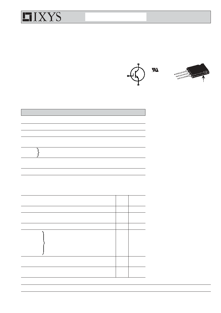
IGBT
Symbol
Conditions
Maximum Ratings
V
CES
T
VJ
= 25∞C to 150∞C
1200
V
V
GES
±
20
V
I
C25
T
C
= 25∞C
95
A
I
C90
T
C
= 90∞C
60
A
I
CM
V
GE
=
±
15 V; R
G
= 22
; T
VJ
= 125∞C
100
A
V
CEK
RBSOA, Clamped inductive load; L = 100 µH
V
CES
t
SC
V
CE
= 900 V; V
GE
=
±
15 V; R
G
= 22
; T
VJ
= 125∞C
10
µs
(SCSOA)
non-repetitive
P
tot
T
C
= 25∞C
375
W
Symbol
Conditions
Characteristic Values
(T
VJ
= 25
∞
C, unless otherwise specified)
min.
typ.
max.
V
CE(sat)
I
C
= 60 A; V
GE
= 15 V; T
VJ
= 25∞C
2.1
2.7
V
T
VJ
= 125∞C
2.5
V
V
GE(th)
I
C
= 2 mA; V
GE
= V
CE
4.5
6.5
V
I
CES
V
CE
= V
CES
;
V
GE
= 0 V; T
VJ
= 25∞C
0.1
mA
T
VJ
= 125∞C
0.1
mA
I
GES
V
CE
= 0 V; V
GE
=
±
20 V
200
nA
t
d(on)
150
ns
t
r
60
ns
t
d(off)
700
ns
t
f
50
ns
E
on
7.2
mJ
E
off
6.0
mJ
C
ies
V
CE
= 25 V; V
GE
= 0 V; f = 1 MHz
3.8
nF
Q
Gon
V
CE
= 600 V; V
GE
= 15 V; I
C
= 50 A
500
nC
R
thJC
0.33 K/W
R
thJH
0.66
K/W
Inductive load, T
VJ
= 125∞C
V
CE
= 600 V; I
C
= 60 A
V
GE
= ±15 V; R
G
= 22
I
C25
= 95 A
V
CES
= 1200 V
V
CE(sat) typ.
= 2.1 V
NPT
3
IGBT
in ISOPLUS 247
TM
Advanced Technical Information
IXYS Semiconductor GmbH
Edisonstr. 15,
D-68623 Lampertheim
Phone: +49-6206-503-0, Fax: +49-6206-503627
IXYS Corporation
3540 Bassett Street, Santa Clara CA 95054
Phone: (408) 982-0700, Fax: 408-496-0670
IXER 60N120
E
C
G
G
C
E
G = Gate
C = Collector
E = Emitter
*Patent pending
Isolated Backside*
ISOPLUS 247
TM
E153432

2 - 2
© 2002 IXYS All rights reserved
IXER 60N120
ISOPLUS 247 OUTLINE
Dim.
Millimeter
Inches
Min.
Max.
Min. Max.
A
4.83
5.21
.190 .205
A
1
2.29
2.54
.090 .100
A
2
1.91
2.16
.075 .085
b
1.14
1.40
.045 .055
b
1
1.91
2.13
.075 .084
b
2
2.92
3.12
.115 .123
C
0.61
0.80
.024 .031
D
20.80
21.34
.819 .840
E
15.75
16.13
.620 .635
e 5.45 BSC
.215 BSC
L
19.81
20.32
.780 .800
L1
3.81
4.32
.150 .170
Q
5.59
6.20
.220 .244
R
4.32
4.83
.170 .190
S
13.21
13.72
.520 .540
T
15.75
16.26
.620 .640
U
1.65
3.03
.065 .080
1 Gate, 2 Drain (Collector)
3 Source (Emitter)
4 no connection
Component
Symbol
Conditions
Maximum Ratings
T
VJ
-55...+150
∞
C
T
stg
-55...+125
∞
C
V
ISOL
I
ISOL
1 mA; 50/60 Hz
2500
V~
F
C
mounting force with clip
20...120
N
Symbol
Conditions
Characteristic Values
min.
typ.
max.
C
p
coupling capacity between shorted
30
pF
pins and mounting tab in the case
Weight
6
g