 | ÐлекÑÑоннÑй компоненÑ: IRVR101 | СкаÑаÑÑ:  PDF PDF  ZIP ZIP |
Äîêóìåíòàöèÿ è îïèñàíèÿ www.docs.chipfind.ru
www.irf.com
Preliminary Data Sheet
1
International
Preliminary Data Sheet
Rectifier
IRVR101
LIN Controlled Alternator Voltage Regulator
Features:
·
9600 Baud Rate
·
10.7 to 16.0V Setpoint Control
·
Programmable Load Response
Control
·
Programmable Field Excitation
·
Full Diagnostic Capability
·
Self Excitation
·
Short Circuit Protected
·
EMI and ESD Immunity
·
Field Excitation, Temperature, and
Fault Status Feedback
·
< 200uA Standby Current
Description
The IRVR101 is an integral alternator voltage regulator that allows for external control of the setpoint voltage in
an automotive charging system where optimized alternator output control is desired. The setpoint control is
achieved using the Local Interconnect Network (LIN) serial communications protocol. Slew rate control and
filtering of the interface lines provide electromagnetic compatibility. The regulator consists of a control ASIC,
discrete low side power MOSFET (field driver), re-circulation diode, and passive components. The discrete
circuitry allows for optimal flexibility with respect to the alternator rotor circuit and charging system
requirements. The IRVR101 is characterized over the temperature range of 40
o
C to 150
o
C.
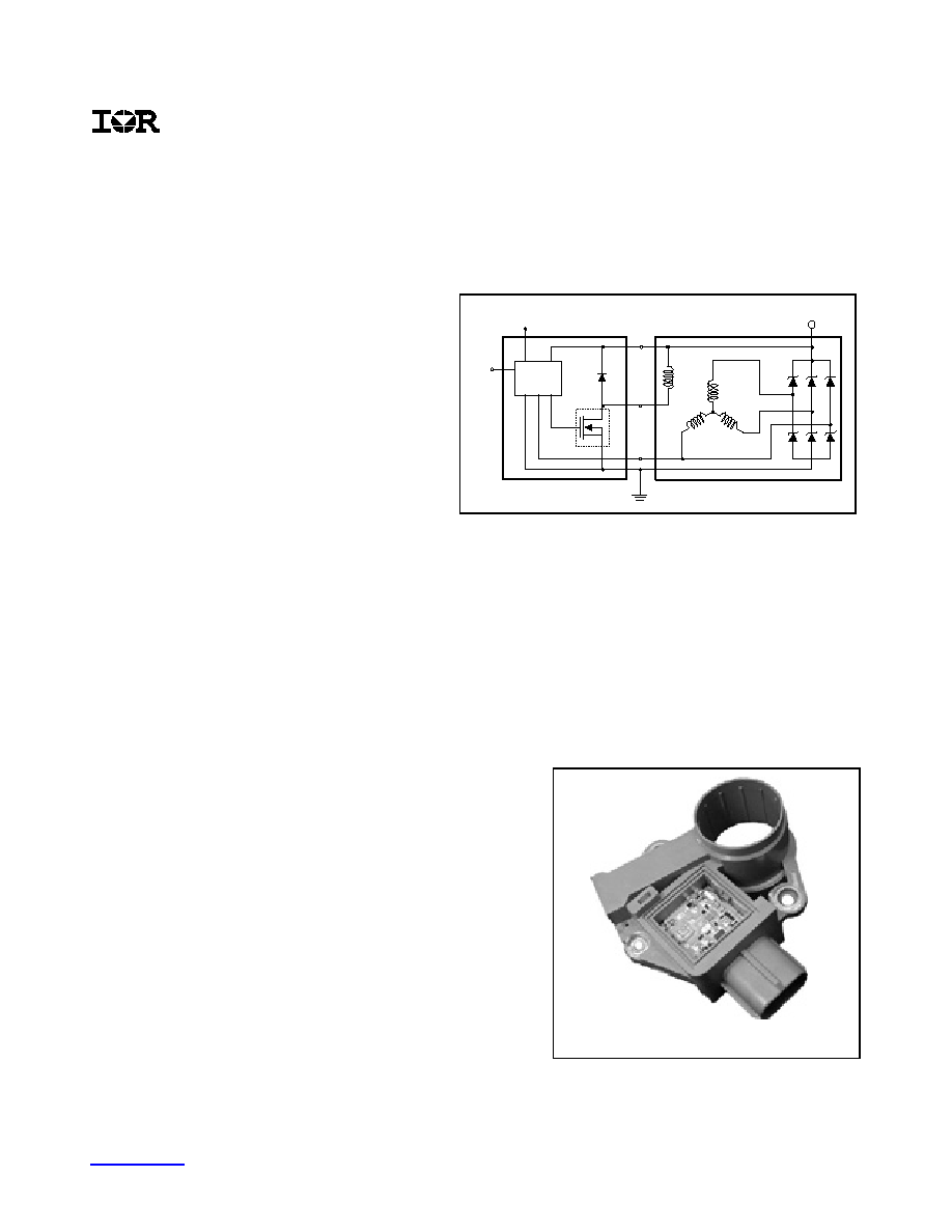
Design
The IRVR101 is manufactured using thick-film hybrid technology.
The hybrid circuit can be customized for your application to
optimize performance and reliability. The hybrid circuit can also
be assembled in a custom housing with an insertmolded lead-
frame specifically designed for flame-soldering or heavy wire
bonding. Thick-film hybrid technology offers reliable high
temperature operation with excellent parametric stability over the
entire operating temperature range. Resistor values are trimmed
within +/-1% using laser equipment that provides precise
calibration of voltage and current sensing circuitry. The control IC
is attached to the substrate using flip chip technology in order to
optimize space and reliability. Bare die is also used for the low
side field driver and re-circulation diode in order to optimize
space and heat transfer.
Voltage Sense
Phase Sense
F
B+
B+
RECTIFIER
ROTOR
STATOR
Control
Circuitry
Field
Driver
LIN
Fly back
Diode
VOLTAGE REGULATOR
ALTERNATOR
P
Voltage Sense
Phase Sense
F
B+
B+
RECTIFIER
ROTOR
STATOR
Control
Circuitry
Field
Driver
LIN
Fly back
Diode
VOLTAGE REGULATOR
ALTERNATOR
P
Custom Thick-film Hybrid Module
www.irf.com
Preliminary Data Sheet
2
International
Rectifier
IRVR101
Introduction
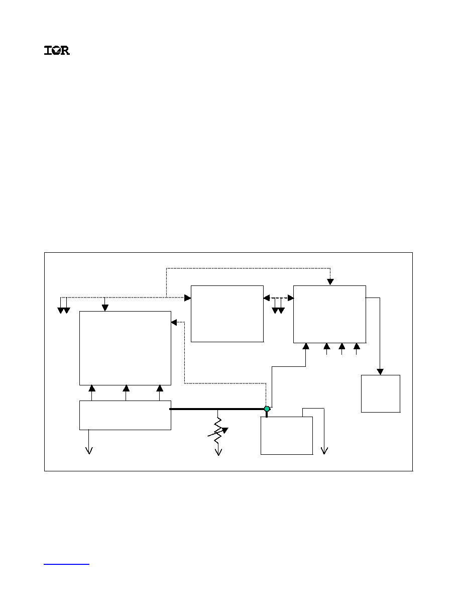
The IRVR101 is designed for use in a 12V automotive charging system where optimized battery charging and
dynamic alternator control are desired. The Block Diagram illustrates the main components and potential
system configuration of the LIN controlled charging system. The regulator is shown separate from the
alternator assembly but it is typically integrated into the machine. The interface between the Engine Control
Unit (ECU) and the regulator requires one bi-directional line with a transceiver at each end for serial
communication. Alternatively, communication may be achieved between the regulator and Body Control
Module (BCM) as illustrated in below.
The signals to the regulator (received from the ECU or BCM) include the voltage setpoint, load response control
ramp, load response control ramp cut-off speed, and the field excitation limit. The voltage setpoint command
also allows for disabling of the field driver to achieve a momentary no output condition. Signals from the
regulator (transmitted to the ECU or BCM) include the field excitation duty cycle, the field excitation current OR
temperature (customer defined), and the fault status. Transmitted fault codes provide unique indication for
mechanical, electrical, temperature, communication, and timeout errors.
Block Diagram
Sensor data inputs *:
ECT =Engine Coolant Temp;
AT = A mbient Temperature;
VSS = Vehicle Speed Sensor
Instrument
Panel
Warning
indicator
Additional
LIN nodes
(up to 15)
LIN Controlled
Voltage Regulator
Alternator
12V Battery
LIN Transceiver
Battery
Voltage
Sense
Body Control
Module (BCM)
LIN
Transceiver
P ower
Input
Stator
Rotor
B+
GND
P hase
detection
Low side
field driver
+
-
B+
Voltage
Sense
Lamp
control
Engine Electronic
Control Unit
CAN
Transceiver
CAN
Transceiver
VSS
AT
ECT
Sensor data inputs *
Vehicle
electrical
loads
Additional
CAN nodes
Optional communication path
LIN
Transceiver
Optional sense line
Sensor data inputs *:
ECT =Engine Coolant Temp;
AT = A mbient Temperature;
VSS = Vehicle Speed Sensor
Instrument
Panel
Warning
indicator
Instrument
Panel
Warning
indicator
Additional
LIN nodes
(up to 15)
LIN Controlled
Voltage Regulator
Alternator
12V Battery
LIN Transceiver
Battery
Voltage
Sense
Body Control
Module (BCM)
LIN
Transceiver
P ower
Input
Stator
Rotor
B+
GND
P hase
detection
Low side
field driver
+
-
B+
Voltage
Sense
Lamp
control
Engine Electronic
Control Unit
CAN
Transceiver
CAN
Transceiver
VSS
AT
ECT
Sensor data inputs *
Vehicle
electrical
loads
Additional
CAN nodes
Optional communication path
LIN
Transceiver
Optional sense line

www.irf.com
Preliminary Data Sheet
3
International
Rectifier
IRVR101
Interface Design
The interface design is based on the LIN communication protocol. Detailed information regarding this
communication protocol can be found in the latest revision of the LIN Specification Package. This package can
be obtained from the LIN Website located at www.lin-subbus.org.
Activation and De-activation
The voltage regulator is activated by a wake up signal that consists of the character `0x80'. The regulator is
also capable of waking up with the presence of any normal bus activity. Once the regulator has been
activated, the regulator will wait until a valid message is received prior to turning on the field driver. The
regulator will then hold the field duty cycle at 18.75% until a cut-in phase signal is recognized at which time the
regulator will soft start ramp to normal regulation. The cut-in phase voltage and frequency must be greater than
2V and 1200 Generator RPM (GRPM) respectively. De-activation requires a bus timeout in combination with a
phase signal timeout. Bus timeout occurs 2s after the last valid message is received. Phase signal timeout
occurs 500mS after the phase voltage and frequency have fallen below 0.6V AND 600 GRPM, respectively.
Self-excitation
In the event of a LIN bus fault, the voltage regulator is capable of self-excitation if a phase voltage and
frequency of greater than 0.6VAND 1200 Generator RPM is detected. This signal is only possible if the
residual magnetism in the alternator rotor core is sufficient enough to generate a magnetic field capable of
inducing the voltage signal in the stator windings. If this signal is detected, the regulator will apply an 18.75%
duty cycle until the cut-in phase signal is recognized at which time the regulator will soft start ramp to default
regulation. The regulator will return to sleep mode at any time when the phase signal has timed out as
described above.
Voltage Sensing
System voltage sensing can be achieved via the dedicated battery sense input or through machine sensing
from the rectifier B+ output via the F+ input to the regulator. The battery sense input is optional and can be
deleted. If the battery sense option is exercised, an open or short circuit at this input will cause voltage sensing
to transfer to the machine voltage sense input (an electrical fault can be indicated if the regulator is configured
for this fault option). The machine voltage setpoint can be set to a different value than the battery sense voltage
to compensate for system voltage variation between the alternator and the battery.
Voltage Regulation
Voltage regulation is achieved using fixed frequency pulse width modulation. The base frequency is typically
150 Hz and the proportional control range for regulation is 100mV. This provides for very stable regulation over
the entire speed and electrical load range.
Load Response Control
Load response control is programmable and can be varied from 0.426 seconds to 13.2 seconds in 16 steps.
Additionally, the load response control cut-off speed is programmable and can be set to "always active" or
varied from 2400 to 8000 Generator RPM. The load response at startup is equal to the programmed value for
the load response control. The load response will always be executed on the first ramp to full field after engine
start regardless of frequency in order to assist in achieving a smooth engine start.
Fault Detection
Respective fault codes are transmitted per the "Fault Detection" table. A 500mS delay is enforced prior to the
transmission of any fault code. Mechanical faults are based on the frequency detection of the stator phase
signal. Electrical faults are based on the voltage detection of the stator phase and system voltage sense inputs.
A temperature fault is based on the regulator IC junction temperature. Communication errors are detected after
a delay of 2s. Examples of sync communication errors are sync bit, checksum, and bit detect errors. A sync bit
error is detected when the sync field does not = `0x55'. A checksum error is generated when the sum of the
modulo-256 sum over all data bytes and the checksum byte do not equal `0xFF'. A bit error is detected when a
transmitted bit does not correspond to the appropriate bus state due to another device forcing the bus to a

www.irf.com
Preliminary Data Sheet
4
different state. Bus timeout errors are detected for any lack of a valid signal within a 2s time frame.
www.irf.com
Preliminary Data Sheet
5
International
Rectifier
IRVR101
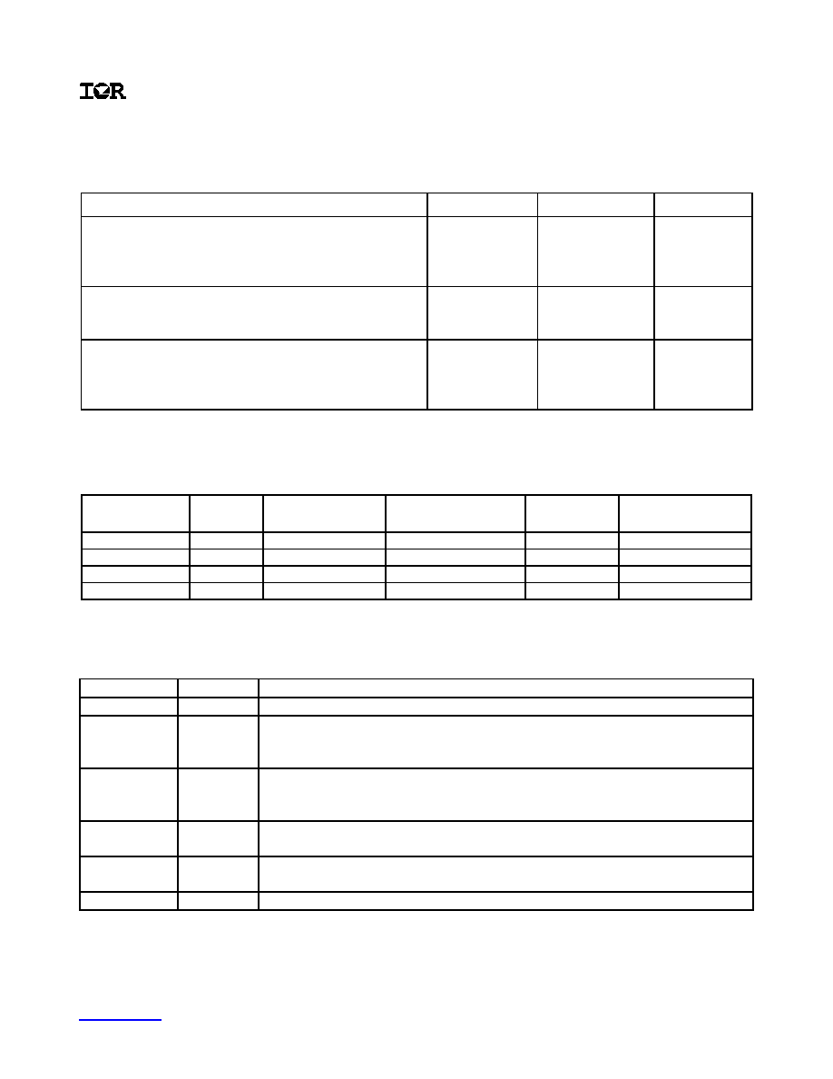
Absolute Maximum Ratings
Absolute Maximum Ratings indicate sustained limits beyond which damage to the device may occur.
All voltage parameters are referenced to GROUND pin . T Ambient = 25 °c unless otherwise specified .
Condition Symbol
Rating
Unit
Power Supply
Continuous DC Voltage
Transient Voltage (load dump)
Reverse Battery (connector/other terminals)
V
BATT
V
MAX
V
MIN
25
40
-12/-3
V
V
V
Temperature
Operating baseplate temperature
Storage temperature
T
A
T
STG
-40 to +150
-50 to +170
o
C
o
C
Field Current
Continuous @ -40
o
C
Continuous @ 25
o
C
Continuous @ 150
o
C
I
FLD-40
I
FLD+25
I
FLD+150
11
8
5
A
A
A
Signal Characteristics
SIGNAL
TYPE
FREQUENCY
RANGE
NORMAL
VOLTAGE RANGE
MAXIMUM
VOLTAGE
QUIESCENT
CURRENT DRAIN
S
DC
N/A
12.5 to 16.0V
100V
100uA
C
PCM
9600 Hz
0.2 to 15.0V
100V
N/A
F-
PWM
100-150 Hz
0.5 to 17.0V
100V
100uA
P
AC
0-2000 Hz
-1 to 17V
100V
N/A
Terminal Functions
Pin Name
Symbol
Description
LIN
C
Serial communication input/output
B+ Voltage
Sense
B+
Alternator rectifier output. Provides machine voltage sense input and
power supply input to regulator. Also used as re-circulation diode
cathode connection.
Battery
Voltage
Sense
S
Optional input for remote battery voltage sensing
Low Side
Field Driver
F-
Low side of alternator field coil. Connected to the drain of the FET when
using a low side drive.
Phase
Detection
P
Stator phase input to the regulator. Used for self-excitation and fault
detection.
Ground
G
Ground connection