 | ÐлекÑÑоннÑй компоненÑ: IRPT2056x | СкаÑаÑÑ:  PDF PDF  ZIP ZIP |
Äîêóìåíòàöèÿ è îïèñàíèÿ www.docs.chipfind.ru
page 1
IRPT2056A
TM
Power Module for 3 hp Motor Drives
IRPT2056A
PRELIMINARY
· 3 hp (2.2 kW) power output
Industrial rating at 150% overload for 1 minute
· 180-240V AC input, 50/60 Hz
· 3-phase rectifier bridge
· 3-phase, short circuit rated, ultrafast IGBT inverter
· HEXFRED ultrafast soft recovery-freewheeling diodes
· Brake IGBT and diode
· Low inductance (current sense) shunts in positive
and negative DC rail
· NTC temperature sensor
· Pin-to-baseplate isolation 2500V rms
· Easy-to-mount two-screw package
· Case temperature range -25
°
C to 125
°
C operational
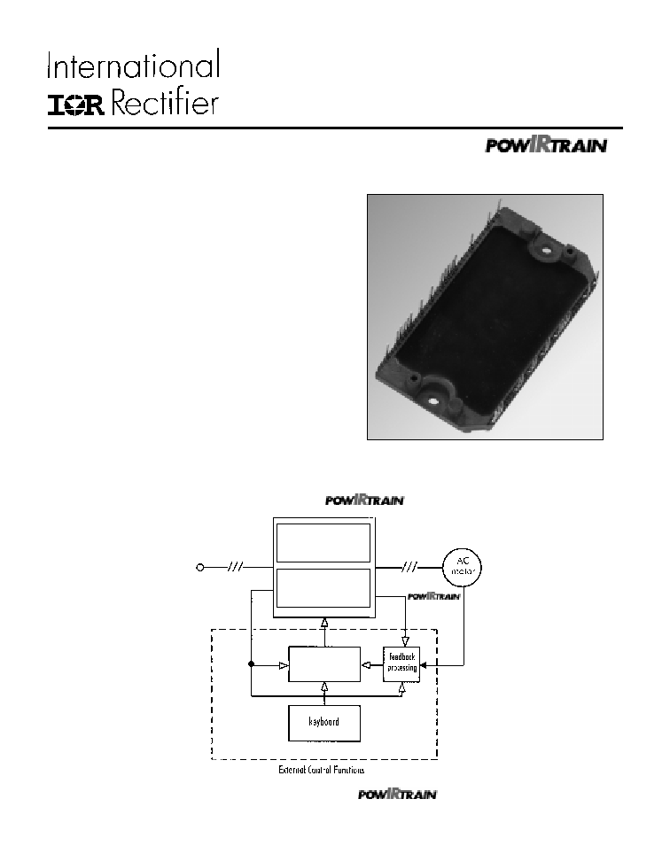
Figure 2. The power module and
within a
motor control system
Figure 1. IRPT2056A Power Module
IRPT2056C
IRPT 2056A
Power
Module
IRPT 2056D
Driver-
Plus
Board
PWM
generator
180-240V
3-phase input
PWM
variable
frequency
output
feedback
(non-isolated)
PD 6.099
page 2
IRPT2056A
System Description
Power Module
The IRPT2056A Power Module, shown in figure 1, is a chip
and wire epoxy encapsulated module. It houses input rectifiers,
output inverter, current sense shunts and NTC thermistor. The 3-
phase input bridge rectifiers are rated at 800V. The brake circuit
uses 600V IGBT and freewheeling diode. The inverter section
employs 600V, short circuit rated, ultrafast IGBT's and ultrafast
freewheeling diodes. Current sensing is achieved through 25
m
low inductance shunts provided in the positive and negative
DC bus rail. The NTC thermistors provide temperature sensing
capability. The lead spacing on the power module meets UL840
pollution level 3 requirements.
The power circuit and layout within the module are carefully
designed to minimize inductance in the power path, to reduce
noise during inverter operation and to improve the inverter
efficiency. The Driver-Plus Board required to run the inverter
can be soldered to the power module pins, thus minimizing
assembly and alignment. The power module is designed to be
mounted to a heat sink with two screw mount positions, in order
to insure good thermal contact between the module substrate and
the heat sink.
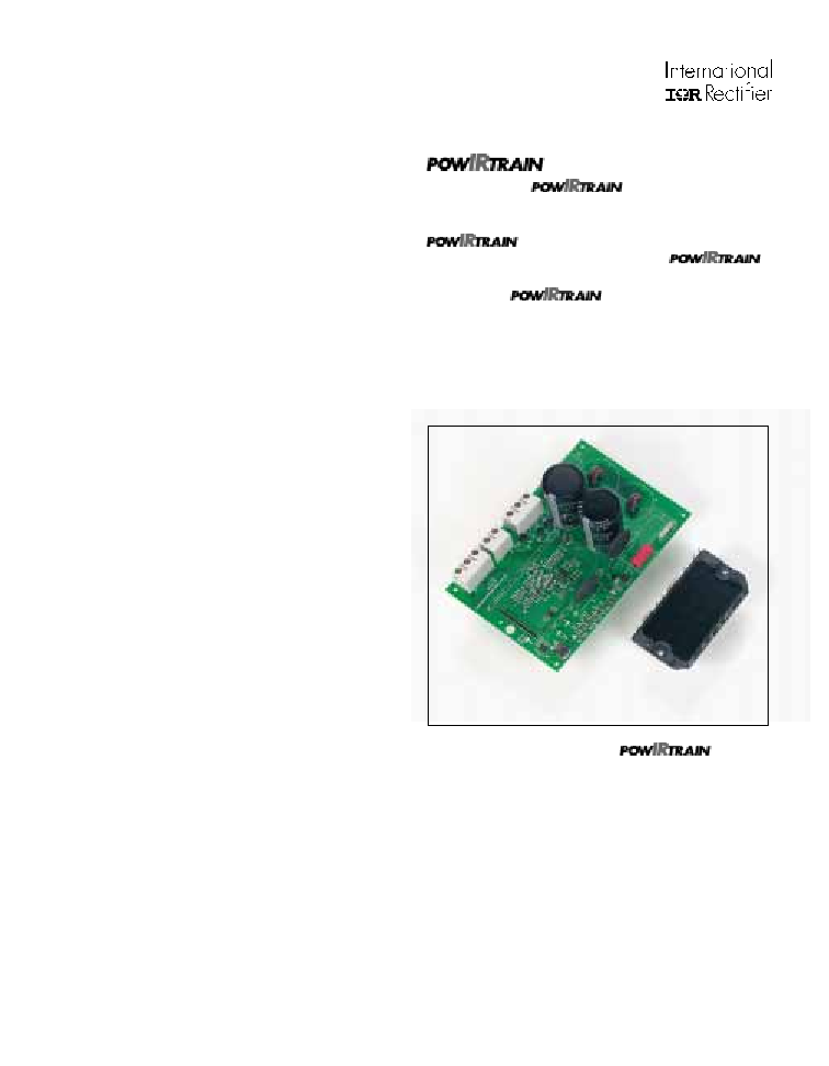
and Design Kit
The IRPT2056C
(Figure 3) provides the
complete power conversion function for a 3 hp (2.2 kW) variable
voltage, variable frequency AC motor controller. The
combines the Power Module (IRPT2056A)
with a Driver-Plus Board (IRPT2056D). The
Design Kit, IRPT2056E includes the following:
· Complete
integrated power stage
· Specification and operating instructions
· Bill of materials
· Electrical schematic
· Mechanical layout of the Driver-Plus Board
· Software transferrable file for easy design integration
· Application information and layout considerations
Figure 3. IRPT2056C

page 3
IRPT2056A
PARAMETERS
VALUES
CONDITIONS
Input Power
Voltage
220V AC, -15%, +10%, 3-phase
Frequency
50/60 Hz
Current
15.4A rms @ nominal output
T
A
= 40
°
C, R
thSA
= 0.42
°
C/W
I
FSM
400A
10ms half-cycle, non-repetitive surge
Output Power
Voltage
0-230V rms
defined by external PWM control
Nominal motor hp (kW)
3 hp (2.2 kW) nominal full load power
V
in
= 230V AC, f
pwm
= 4kHz,
150% overload for 1 minute
f
o
= 60 Hz,
Nominal motor current
11A nominal full load power
T
A
= 40
°
C, R
thSA
= 0.42
°
C/W
16.5A 150% overload for 1 minute
DC Link
DC link voltage
400V maximum
Brake
Current
20A
Sensor
Temp. sense resistance
50 kOhms
±
5%
@ T
NTC
= 25
°
C
3.1kOhms
±
10%
@ T
NTC
= 100
°
C
Current sense
25mOhms
±
5%
@ T
SHUNT
= 25
°
C
Protection
IGBT short circuit time
10
µ
s
DC bus = 400V, V
GE
= 15V,
line to line short
Recommended short circuit-
70A peak
shutdown current
Gate Drive
Q
G
120 nC (typical)
@ V
GE
= 15V, refer figure 5b
Recommended gate driver
IR2133 (see Figure 10)
Module
Isolation voltage
2500V rms
pin-to-baseplate, 60 Hz, 1 minute
Operating case temperature
-25
°
C to 125
°
C
95% RH max. (non-condensing)
Mounting torque
1 Nm
M4 screw type
Storage temperature range
-40
°
C to 125
°
C
Soldering temperature for 10 sec. 260
°
C maximum
at the pins (.06" from case)
Specifications
page 4
IRPT2056A
1
4
8
12
16
20
24
20
40
60
80
100
120
140
160
180
200
Power
100%
Power
150%
RthSA 150% Load (1 min.)
10-60 Hz
RthSA 100% Load Continuous
10-60 Hz
RthSA 150% Load (1 min.)
Down to 3 Hz
2 hp
(1.5 kW)
PWM Frequency (kHz) (Induction Motor Load)
Thermal Resistance (R
thSA
°
C/W)
Total Power Dissipation (Watts)
0.2
0.3
0.4
0.5
0.7
0.8
0.9
0.6
0
0.1
0
1
4
8
12
20
0
50
100
150
200
250
300
Power
100%
Power
150%
RthSA 150% Load
1 min.)10-60 Hz
RthSA 100% Load Continuous
10-60 Hz
PWM Frequency (kHz) (Induction Motor Load)
RthSA 150% Load (1 min.)
Down to 3 Hz
3 hp
(2.2 kW)
16
24
Thermal Resistance (R
thSA
°
C/W)
Total Power Dissipation (Watts)
0
0.1
0.3
0.5
0.4
0.2
0.6
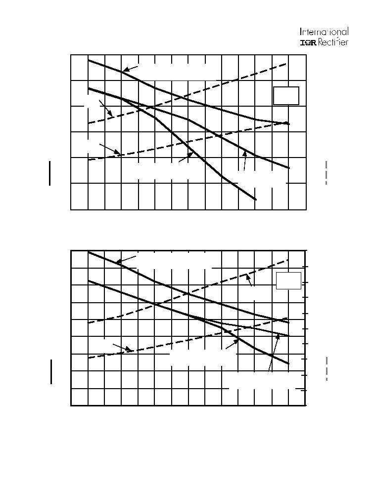
Figure 4a. 3hp/11A output Heat Sink Thermal Resistance and Power Dissipation vs. PWM Frequency
Figure 4b. 2hp/8A output Heat Sink Thermal Resistance and Power Dissipation vs. PWM Frequency
NOTE: For Figures 4a and 4b: Operating Conditions: V
in
= 230V
rms
, MI =1.15, PF = 0.8, TA
= 40
°
C, Tj < 145
°
C, Ts < 95
°
C, Z
thSA
limits
T
c
during 1 minute overload to 10
°
C
page 5
IRPT2056A
1
10
100
0
500
1000
1500
2000
2500
3000
V , Collector-to-Emitter Voltage (
C,
C
a
p
a
citan
c
e (pF
)
CE
C
ies
C
oes
C
res
V
C
C
C
=
=
=
=
0V,
C
C
C
f = 1MHz
+ C
+ C
C SHORTED
GE
ies
ge
gc , ce
res
gc
oes
ce
gc
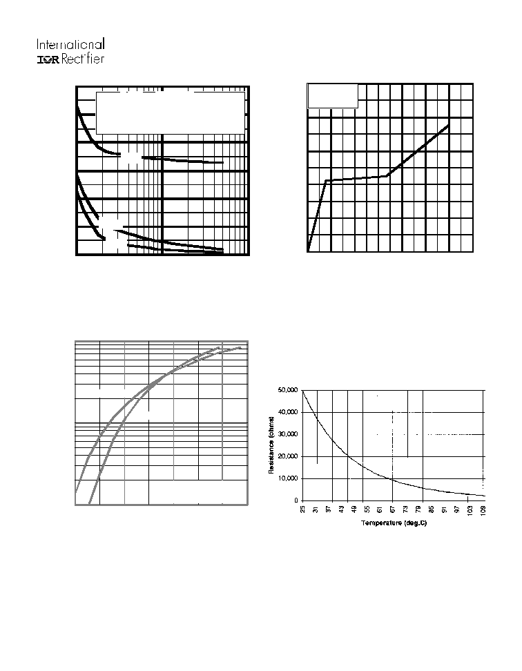
Figure 5a. Typical Capacitance vs
Collector-to-Emitter Voltage
Figure 5b. Typical Gate Charge vs
Gate-to-Emitter Voltage
Figure 5c. Typical Transfer Characteristics
Figure 6.
Nominal R-T Characteristics of the
NTC Thermistor
0
20
40
60
80
100
120
140
0
4
8
12
16
20
Q , Total Gate Charge (nC)
G
V , Ga
te-to-Em
itter V
o
lta
g
e
(V)
GE
V
= 400V
I
= 25A
CC
C
1
10
100
5
7
9
11
C
I
,
C
o
l
l
e
c
t
o
r-
t
o
-
E
mit
t
e
r
Cu
rr
e
n
t
(
A
)
GE
V , Gate-to-Emitter Voltage (V)
T = 25
°
C
J
T = 150
°
C
J
V = 50V
5
µ
s PULSE WIDTH·
CC
A