Microsoft Word - IRISMPS5_USERGUIDE_Rev1.doc

IRISMPS5
www.irf.com
REFERENCE DEMO BOARD
MODEL : IRISMPS5
DOCUMENT Name : IRISMPS5_USERGUIDE_Rev2
PN:1950-1001_Rev.2
DATE : 5/28/2004
Page 1 of 11
IRISMPS5 DEMO BOARD USER GUIDE
INTRODUCTION :
The IRISMPS5 is an open frame
90W Flyback power supply unit
(psu) using the IRIS4015
Integrated switcher. This demo
board aims to show the capability
of the IRIS4015 to handle the
upper level of flyback topology
power range, without the strict
standby power requirement. It
works with the wide range of input
AC voltage (universal) and has a
single output of +15V / 6amp.
Switching frequency varies
according to line and load
condition. It operates in quasi-
resonant mode ( switching current
is in critically discontinuous mode)
at rated capacity. This switching
technique enables the internal
power mosfet of IRIS4015 to
switch at variable frequency with
minimum switching loss.
SPECIFICATION DATA
1. AC Input: V=90~265V, f=50-60Hz,
Iinac= 2.2 Arms max
2. Efficiency: Typical 83% @230Vac
measured at max. load 6 Amp (90W)
3. Switching Frequency: 40-390kHz
4. Vout : +15V nominal (14.55 � 15.45)
5. Iout : 0 - 6Amax
6. Ripple & Noise :<450mVpp
7. Hold-Up Time: 20msec (230Vin Full
load) / 10ms (115Vin Full load)
8. Output Risetime: 15ms max @ 115Vac
9. Short Circuit Protection: Yes
10. Overvoltage Protection : Yes
INPUT / OUTPUT CONNECTIONS
Input :
CON1 : 3-PIN CONNECTOR (MIDDLE PIN IS VOID [pin 2])
Pin 1 & 3 : AC Voltage ( 90 � 265, 50-60Hz)
Output :
CON2 : 4�PIN CONNECTOR
Pin 1 � 2 : ++ Positive 15V
Pin 3 - 4 : - - Negative
IRISMPS5
www.irf.com
REFERENCE DEMO BOARD
MODEL : IRISMPS5
DOCUMENT Name : IRISMPS5_USERGUIDE_Rev2
PN:1950-1001_Rev.2
DATE : 5/28/2004
Page 2 of 11
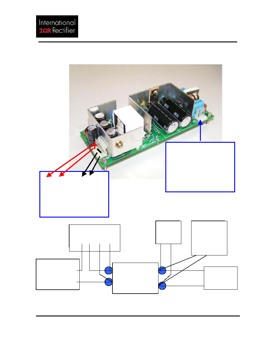
CONNECTION DIAGRAM
Figure 1 : Recommended test setup
CON1
Pin 1 & 3
(MIDDLE PIN-2 VOID)
Input from AC
Power source
+ +
- -
Pin 1-2 Pin 3-4
CON2
DC Output Load
0 � 6Amp
(Pin)
Power Meter
+Iin -Iin -Vin +Vin
Sense
AC1
AC Prog Source
or Variac
(0 � 265Vac) AC2
(Con1) (Con2)
L +
IRISMPS5
(+15V x 6Amp )
N
-
(V out)
DMM V
+
-
+
E-Load
-
Ripple&Noise
Oscilloscope
(20MHz BW)
+ -
IRISMPS5
www.irf.com
REFERENCE DEMO BOARD
MODEL : IRISMPS5
DOCUMENT Name : IRISMPS5_USERGUIDE_Rev2
PN:1950-1001_Rev.2
DATE : 5/28/2004
Page 3 of 11
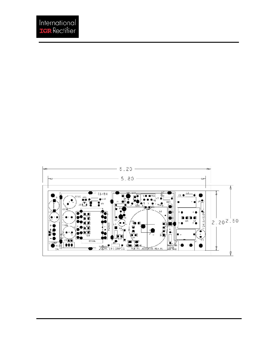
PHYSICAL LAYOUT
The board layout of the IRISMPS5 Demo board is shown in Figure 2. The PCB is a double�sided
FR4 type ( 2oz. copper thickness).
The input of the primary section is consist of the AC input connector, fuse and EMI filter section
which are located at the right side of the board, arranged in a straight forward direction.
Most parts of the primary section ( high voltage area ) are surrounded by the primary heat sink
to which the IRIS4015 integrated switcher is attached with insulation pad. Primary section
also includes the bridge rectifier DB1 and primary bulk cap/s (C5 or C5A//C5B) and primary
side and bias winding of the power transformer.
The major parts in the secondary section are the DC output connector, pi-filter, precision
reference voltage IC U2, secondary heat sink to which the output rectifier is attached with
thermal grease.
The output connector is at the leftmost part of the board. The output is filtered using a pi-filter
consist of low impedance e-caps C13A - C ,inductor L3 and e-cap C15. A ceramic capacitor C16
is located at the backside of the board. This c-cap is positioned nearest at output connector
pads to minimize switching noise.
Figure 2. � Component layer of IRISMPS5 demo board with physical boundary
and dimensions.
IRISMPS5
www.irf.com
REFERENCE DEMO BOARD
MODEL : IRISMPS5
DOCUMENT Name : IRISMPS5_USERGUIDE_Rev2
PN:1950-1001_Rev.2
DATE : 5/28/2004
Page 4 of 11
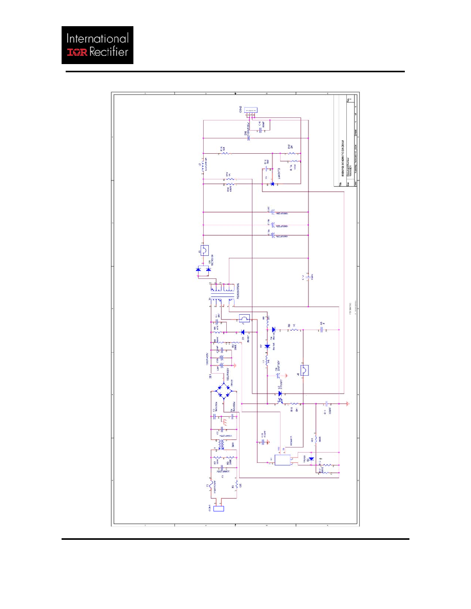
SCHEMATIC DIAGRAM
IRISMPS5
www.irf.com
REFERENCE DEMO BOARD
MODEL : IRISMPS5
DOCUMENT Name : IRISMPS5_USERGUIDE_Rev2
PN:1950-1001_Rev.2
DATE : 5/28/2004
Page 5 of 11
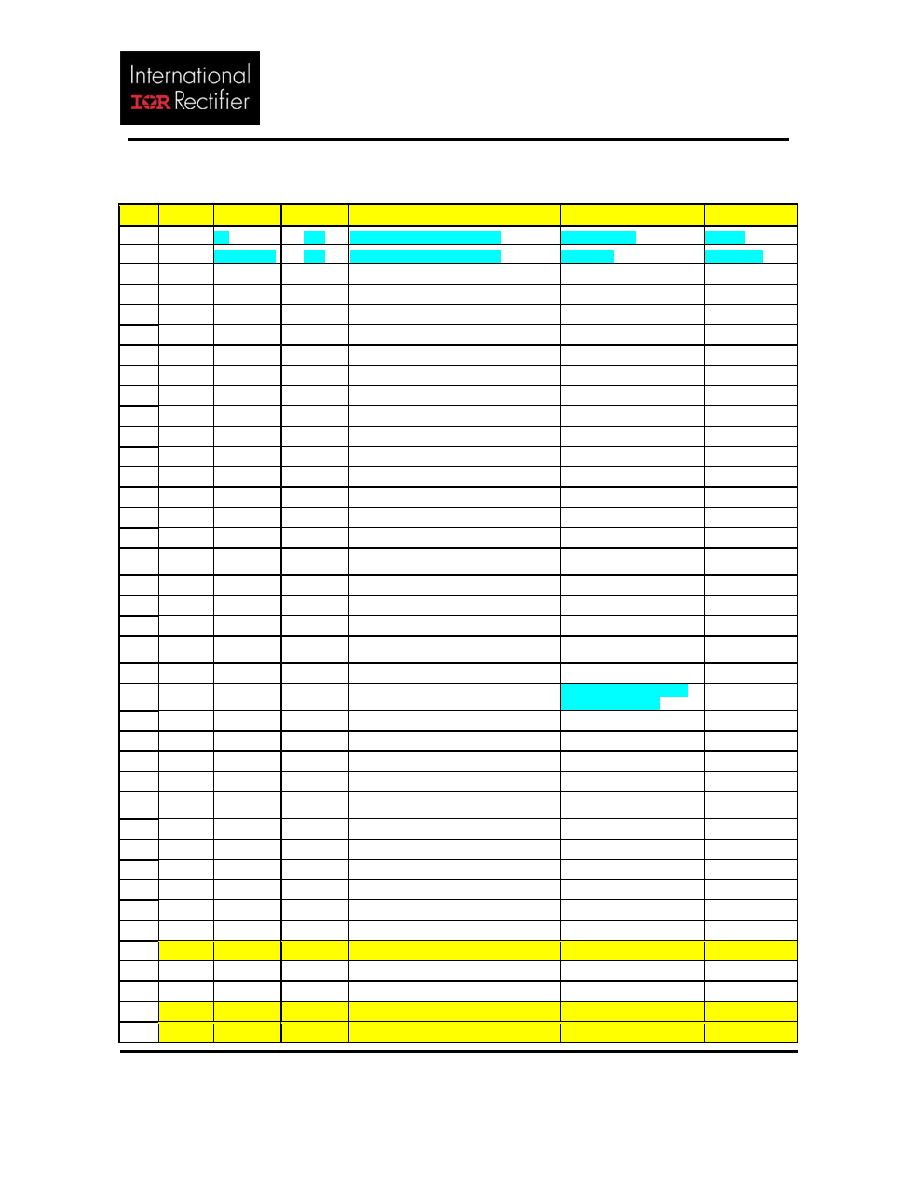
BILL OF MATERIALS
Item
Qty
Reference Part value
Description
Manufacturer PN
Supplier
1 1
R1
10R
NTC Thermistor 10ohm 3Amp
B57235S100M
EPCOS
R1 alternate
10R
NTC Thermistor 10ohm 4Amp
MSP104M
MEGATOR
2
2
R2,R3
390k
1206 SMD Resistor 5%
HJW4J0394T50
ROYAL OHM
3
2
R4,R5
390k
1206 SMD Resistor 5%
HJW4J0394T50
ROYAL OHM
4
1
R6
47K
Metal Oxide Film Resistor 5% 2W
BO2SJ0473A80
ROYAL OHM
5
1
R8
22R
Carbon Film Resistor 5% 1/4W
BCW4J220JA00
ROYAL OHM
6 1 R9 150R
1206
SMD
Resistor
1%
RCT06151FTP
RALEC
7 1 R10 5.1k
1206
SMD
Resistor
1%
RCT06512FTP
RALEC
8
1
R12
0R15
1206 SMD Resistor 5%
SR733ALTER15J
KOA
9
1
R13
*unstuffed ( 1206 SMD Resistor 5% )
10 1 R11 390R
1206
SMD
Resistor
1%
RCT06391FTP
RALEC
11 1 R14 430R
1206
SMD
Resistor
1%
RCT06431FTP
RALEC
12 1 R15
1k
1206
SMD
Resistor
1%
RCT06102FTP
RALEC
13 1 R16 10k
1206
SMD
Resistor
1%
RCT06103FTP
RALEC
14 1 R17
2k
1206
SMD
Resistor
1%
RCT06202FTP
RALEC
15 1 R17A 100k
1206
SMD
Resistor
1%
RCT06104FTP
RALEC
16 0
C1, C2
Alternate
330 nF
275VAC X2 EMI cap
KNB1560 0.33UF 10% 275
L30 R15
ISKRA
17
2
C1, C2
330 nF
275VAC X2 EMI cap
PHE840MB6330MB14R17 EVOX RIFA
18
3
C3, C4, C12
1n5
250VAC Y1 ceramic disc capacitor
KNB2520 1N5 M 250V
ISKRA
19
2
C5A, C5B
150uF
400V AluminumE-cap AXW (DxL, 18x40) 400AXW150M 18X40
RUBYCON
20
*C5
alternate
330 uF
400V E-cap MXR 35mmx35mm
400MXR330MD35
RUBYCON
21
1
*C6
1nF
500V Ceramic disc cap
XC7152KH
PANOVERSEAS
22
1
C7
4n7
2kV Ceramic disc cap
DE1105E472Z2K-SS or
DEBF33D472ZN2A MURATA
23
1
C8
330pF
1206 50V ceramic capacitor
C1206KRX7R9BB331
PHYCOMP
24 1
C9 22uF
35V
Electrolytic
Capacitor
TC04RKMF35VB22MF50
NCC
25
1
C10
470pF
1kV Ceramic Disc Capacitor
DEBB33A471KP2A
MURATA
26
1
C11
330pF
1206 50V ceramic capacitor
C1206KRX7R9BB331
PHYCOMP
27 3
C13A,C13B,
C13C
1000uF
25V Low impedance e-cap ZL
25ZL1000MG4 12.5X25
RUBYCON
28
1
C14
10 nF
1206 50V ceramic capacitor
C1206KRX7R9BB103
PHYCOMP
29
1
C15
1000uF
25V Low impedance e-cap YXG
25YXG1000MG4 10X28
RUBYCON
30
1
C16
100nF
1206 50V ceramic capacitor
C1206KRX7R9BB104
PHYCOMP
31
1
L1
5mH
Common Mode Choke UU16 Line Filter PG0201-3 Rev 2
Pulse Eng'g.
32
1
L2
bead
Leaded ferrite bead ( DxL : 3.5x 5mm)
RH035050ST-B
CHILISIN
33
1
L3
0.76 uH 6.5 turn 8A rod coil Inductor
PG0203
Pulse Eng'g.
34
1
DB1
4GBL08 4amp 800V Bridge rectifier diode
4GBL08
IR
35
1
D1
IN5407
3A, 600V Fast Recovery Rectifier
IN5407
PHILIPS
36
2
D2,D4
L4148
500mW Silicon Epitaxial Diode, SMD
L4148
PHILIPS
37
1
D3
11DQ03 1.1A 30V Schottky Rectifier
11DQ03
IR
38
1
D5
16CTQ100 16A, 100V Schottky Rectifier
16CTQ100
IR