 | ÐлекÑÑоннÑй компоненÑ: SRD00217x | СкаÑаÑÑ:  PDF PDF  ZIP ZIP |
srd00217x.fm
Data Sheet
1
2001-12-01
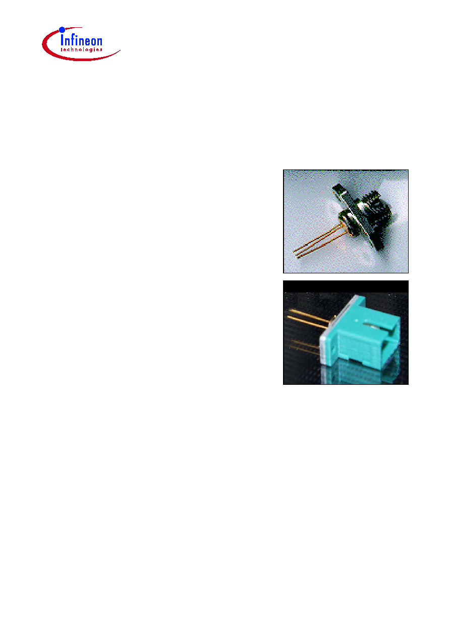
Ternary PIN Photodiode
in Receptacle Package
SRD00217x
SRD00217G
SRD00217N
Fiber Optics
Features
· InGaAs/InP PIN photodiode
· Designed for applications in fiber-optics
communication systems
· Sensitive receiver for 2nd and 3rd optical window
(1300 nm and 1550 nm)
· Suitable for bit rates up to 2.5 Gbit/s
· For singlemode and multimode applications
SONET OC-1...OC-48, SDH STM-1...STM-16
· Low junction and low package capacitance
· Fast switching times
· Low dark current
· Excellent noise immunity
· High reverse current stability from planar structure
· Hermetically sealed TO46 package
SRD00217x
Pin Configuration
Data Sheet
2
2001-12-01
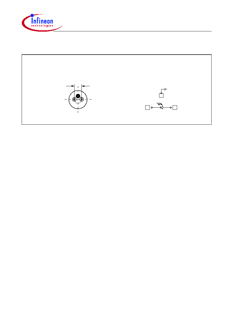
Pin Configuration
Figure 1
Receiver 1
1
2
3
2.54 mm
Receiver 1 (bottom view)
2
3
1
Pinning 1
SRD00217x
Description
Data Sheet
3
2001-12-01
Description
The Infineon optical receiver module has been designed for use in optical networks and
is suitable for bit rates up to max. 2.5 Gbit/s if used without any TIA.
The optical receiver module uses a high-speed PIN photodetector optional coupled with
a hybrid low noise transimpedance amplifier (PIN-TIA). The optical receiver photodiode
can be used for 1310 nm or 1550 nm optical communications.
The PIN photodiode is made of InGaAs/InP and has an active diameter of 75 µm. The
function of the PIN and PIN-TIA optical receiver module is to detect input optical power,
to transduce the incident radiation into current (PIN) and then to convert the current into
a voltage (PIN-TIA).
The low input noise current density of the used transimpedance amplifiers in PIN-TIA's
provides the optical receiver module, when used with appropriate filtering, with ample
sensitivity for realizing minimum input power requirements. Designers of optical
receivers can use the module in any application that benefits from integration of the
photodiode and TIA into a TO coaxial package. Typical for such applications are
receivers for digital crossconnects, digital loop carriers, add/drop-multiplexers and
optical network units.
Last but not least the fast switching times, low dark currents and the packaging in a
compact and hermetically sealed TO46 make the optical receivers usable in many other
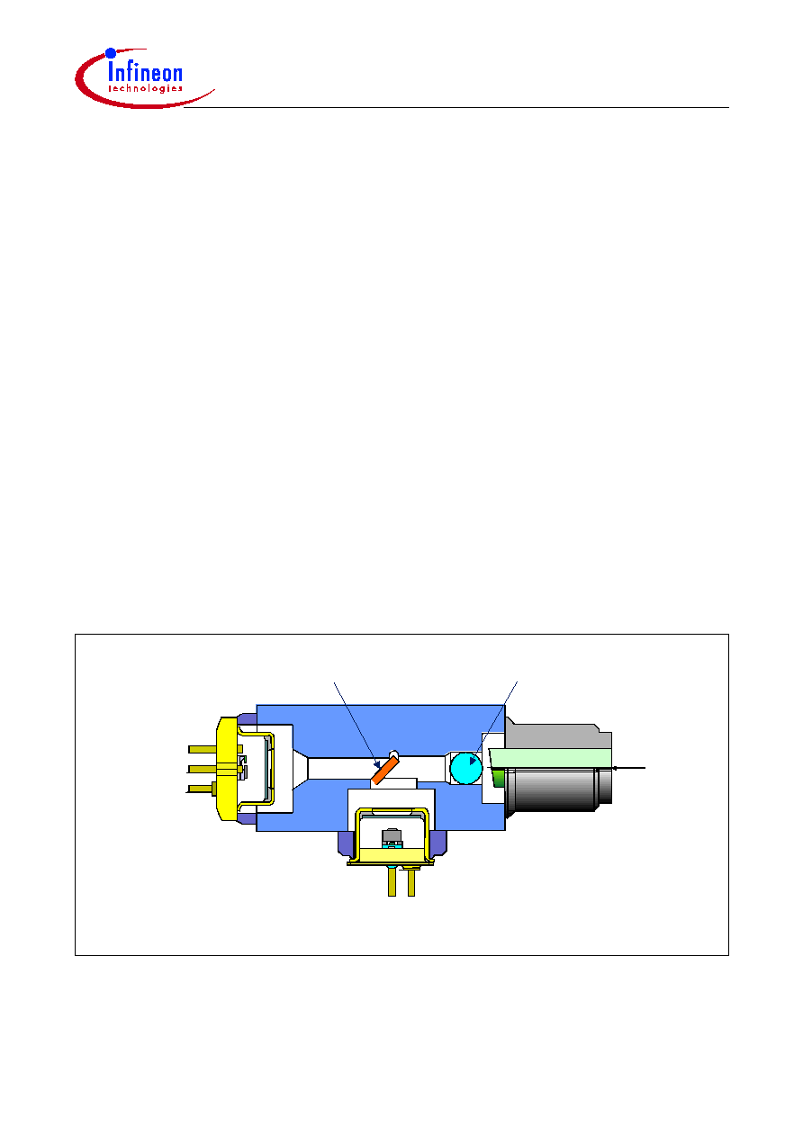
fiber optic receiver applications. One application is the use in a Compact realization of a
transceiver in one module like the so called BIDI
®
(
Figure 2
).
Figure 2
Compact Realization of the Transceiver in One Module
TO-Detector
Glass Lens
Fiber
Beam Splitter
TO-
Laser
SRD00217x
Technical Data
Data Sheet
4
2001-12-01
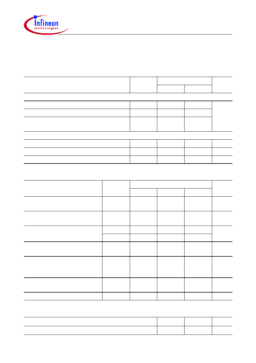
Technical Data
All data refer to the full operating temperature range unless otherwise specified.
Absolute Maximum Ratings
Parameter
Symbol
Limit Values
Unit
min.
max.
Module
Operating temperature range at case
T
C
40
85
°C
Storage temperature range
T
stg
40
85
Soldering temperature (
t
max
= 10 s,
2 mm distance from bottom edge of case)
T
S
260
Receiver Diode
Reverse Voltage
V
R
20
V
Forward Current
I
F
10
mA
Optical power into the optical port
P
port
1
mW
Receiver Diode Electro-Optical Characteristics
Parameter
Symbol
Limit Values
Unit
min.
typ.
max.
Spectral sensitivity
V
R
= 2 V,
P
opt
= 1 µW
S
1310nm
S
1550nm
0.8
0.9
A/W
Change in Spectral Sensitivity in
Operating Temperature Range
S
0.2
%/K
Dark current
V
R
= 2 V,
P
opt
= 0 mW
I
D 25°C
5
nA
I
D 85°C
50
Total Capacitance
V
R
= 3 V,
f
= 1 MHz,
V
RF
= 30 mV
C
0.8
1
pF
Rise and fall time (10%...90%)
V
R
= 5 V,
P
opt
= (0.1...1) mW, 50
t
r
,
t
f
200
300
ps
Cut Off Frequency
= 1310 nm,
V
R
= 5 V, 50
f
3dB
1
GHz
Return Loss,
= 1310 nm
RL
20
dB
End of Life Time Characteristics
Parameter
Symbol
Max.
Unit
Detector Dark Current,
V
R
= 2 V,
T
=
T
max
I
R
400
nA
SRD00217x
Fiber Data
Data Sheet
5
2001-12-01
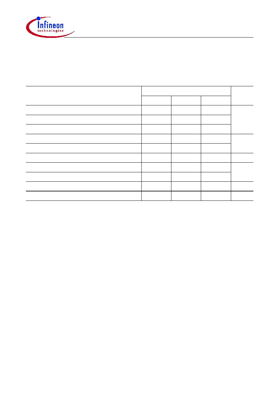
Fiber Data
The mechanical fiber characteristics are described in the following table.
Fiber Characteristics
Parameter
Limit Values
Unit
min.
typ.
max.
Mode Field Diameter
50
µm
Cladding Diameter
123
125
127
Mode Field/Cladding Concentricity Error
1
Cladding Non-circularity
2
%
Mode Field Non-circularity
6
Cut off Wavelength
1270
nm
Jacket Diameter
0.8
1
mm
Bending Radius
30
Tensile Strength Fiber Case
5
N
Length
0.8
1.2
m
Document Outline