 | –≠–ª–µ–∫—Ç—Ä–æ–Ω–Ω—ã–π –∫–æ–º–ø–æ–Ω–µ–Ω—Ç: ILC6301 | –°–∫–∞—á–∞—Ç—å:  PDF PDF  ZIP ZIP |

ILC6301
100mA DC/DC Converter With KeepAliveTM Output
Impala Linear Corporation
Impala Linear Corporation
1
(408) 574-3939
www.impalalinear.com
Feb 2001
ILC6301 1.1
The ILC6301 series of DC-DC converters represents an
advanced generation of energy resource management IC's
for battery operated and portable systems. This device
series showcases the unique ability to power down a pri-
mary load while maintaining power regulation to a second-
ary load that must remain continuously active. Termed
"KeepAliveTM" (KA), this feature can supply auxiliary power
to serial port receivers, command receivers or control sen-
sors (i.e. IR, RF) while holding other system blocks in stand-
by or power-down mode. Main and KATM outputs are user
selected via the SEL pin. Overall device control is accom-
plished with the use of the On/Off pin. Only one output is
active at any time.
Both outputs are fixed at either 3.0V or 3.3V. For economy
and efficiency, the architecture utilizes a single coil to gen-
erate each output. The Main output can supply up to 100mA
and the KeepAliveTM section can supply up to 10mA. Each
regulator performs buck or boost functions depending on
the value of V
DD
. At V
DD
> 3.7V automatic control invokes
chopper mode operation and for V
DD
< 3.7V automatic con-
trol invokes boost mode operation. The operating range for
V
DD
is 1.8V to 6V.
The ILC6301 is available in either the conventional SOIC-8
or the space saving MSOP-8 plastic packaging.
∑ Selectable Main (to 100mA) or KeepAliveTM (to 10mA)
voltage outputs
∑ Input voltage operating range 1.8V to 6.0V
∑ 3.0V or 3.3V fixed output voltages (custom
requirements contact Impala)
∑ Internal controlled synchronous operation requires no
external diode
∑ Optimized design requires a minimum of external components
One inductor and three capacitors
∑ Low power OFF mode, < 1µA @ V
DD
= 1.8V
∑ Internal oscillator frequency ~ 210kHz ±15%
∑ Condition Flag output
∑ Portable and battery operated systems
∑ Remote data collection terminals
∑ Designs requiring continuous communications receive
port monitoring
∑ Systems requiring continuous sensor activation for
event specific detection
∑ Security devices
∑ Low duty cycle, NLS medical instrumentation
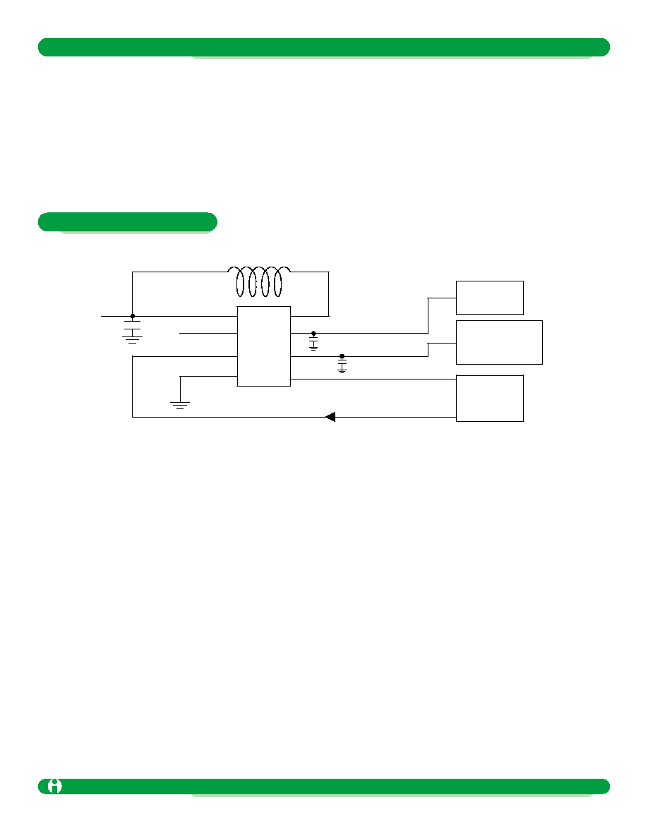
ILC6301
V
DD
C
byp
On/Off
SELect
V
SS
20µF
20µF
Flag Out
V
OUT MAIN
V
OUT KA
L
X
Advance
General Description
Features
Applications
Typical Circuit

Pin Name
V
DD
V
SS
V
OUT MAIN
V
OUT
KeepAlive
On/Off
Select
Flag
L
X
Pin Number
TBD
TBD
TBD
TBD
TBD
TBD
TBD
TBD
Pin Description
Input voltage. i.e. Battery. Positive Relative to V
SS
Common, Ground
Main output voltage. Output bypass capacitor connection
KA output voltage. Output bypass capacitor connection
Digital input activates device. 1 = ON, 0 = OFF
Can be tied to V
DD
Digital input, mode select. 1= Normal, 0 = KeepAlive
Digital Output. Indicates low battery status
Connection for inductor. (inductor returns to V
DD
)
Can be tied to V
DD
Driver-
Control
SWITCHER
KEEP ALIVE
Driver-
Control
SW_OUT
KA_OUT
L
X
Thermal
Input
Control
ON/OFF
SEL
FLAG
KA_ON
Switcher_ON
Phase
Control
Mode
V-REG
V
ref
OSC
V
SS
V
DD
100mA DC/DC Converter With KeepAliveTM Output
Advance
Impala Linear Corporation
2
(408) 574-3939
www.impalalinear.com
Feb 2001
ILC6301 1.1
Pin Description ILC6301
Functional Block Diagram

Symbol
V
OUT, MAIN
V
OUT, KA
-
P
D
T
J(MAX)
T
STG
JA, SOIC
JA, SOIC
Symbol
V
DD
F
O
V
ref
I
OFF
V
mode
Parameter
Voltage on Main V
OUT
pin
Voltage on KA V
OUT
pin
All other pins Ref to V
SS
Continuous Power Dissipation under ANY condition
Maximum Junction Temperature
Storage Temperature
Lead Temperature. Soldering 10 sec
Package Thermal Resistance - SOIC
Package Thermal Resistance - MSOP
Ratings
-0.3 to 7
-0.3 to 7
-0.3 to 7
400
150
-40 to 125
300
154
206
Units
V
V
V
mA
∞C
∞C
∞C
∞C/W
∞C/W
Electrical Characteristics ILC6301
Parameter
Input Voltage
Switch Frequency
Reference Voltage
OFF Mode Current
Switcher to Chop mode threshold
Thermal Shutdown
Min
1.8
180
3.6
142
Typ
200
1.217
150
Max
6.0
240
1µA
3.8
163
Units
V
kHz
V
µA
V
∞C
Comment
V
IN
Trimmed to center
Trimmed Tol. TBD
V
IN
= 1.8. OFF mode active
V
IN
where SW to Chop or Chop to
SW mode change occurs
Hysteresis ~ 20∞C
General and Common Parameters
Parameter
SEL Logic 1
SEL Logic 0
ON/OFF Logic 1
ON/OFF Logic 0
Symbol
V
IH
V
IL
V
IH
V
IL
Min
1.4
1.4
Typ
Max
0.5
0.5
Units
V
V
V
V
Comment
Switcher is selected
KeepAlive is selected
Normal operation
Stand-by operation
Input Parameters
100mA DC/DC Converter With KeepAliveTM Output
Advance
Impala Linear Corporation
3
(408) 574-3939
www.impalalinear.com
Feb 2001
ILC6301 1.1
Absolute Maximum Ratings

Symbol
V
OUT
I
O(MAX)
I
O(MIN)
V
R
EFF
Units
µH
µF
µF
µF
Value
10
20
20
20 (or user TBD)
Parameter
Out Voltage
Output Current, max
Input Current, min
Ripple at max load
Conversion Efficiency
Symbol
V
OUT
I
O(MAX)
I
O(MIN)
V
R
EFF
Min
10
48
Typ
3 or 3.3
Max
100
60
86
Units
V
mA
mA
mV
%
Comment
Mask programmable
Short circuit limiting not enabled
Regulation and ripple percentage
Degrades slightly at lower I
OUT
L
X
and C
OUT
as recommended
Switcher Section Parameters
Parameter
Out Voltage
Output Current, max
Input Current, min
Ripple at max load
Conversion Efficiency
Min
1
Typ
3 or 3.3
85
Max
10
60
Units
V
mA
mA
mV
%
Comment
Fixed
Short circuit limiting not enabled
Regulation and ripple percentage
Degrades slightly at lower I
OUT
Coil and C
OUT
as recommended
KeepAlive Section Parameters
Switcher Section
Coil
Switch out capacitor
KeepAlive
Output capacitor
General
Input bypass capacitor
Recommended Components
Note: Customer may choose to optimize recommended values to suit a given application
100mA DC/DC Converter With KeepAliveTM Output
Advance
Impala Linear Corporation
4
(408) 574-3939
www.impalalinear.com
Feb 2001
ILC6301 1.1
Electrical Characteristics ILC6301
V
DD
ILC6301
C
byp
On/Off
V
SS
20µF
20µF
Flag
Main
KA
L
X
System "ON"
Voltage
Activity Monitoring
System
S-Port, Sensors, etc.
Reset
µP
100mA DC/DC Converter With KeepAliveTM Output
Advance
Impala Linear Corporation
5
(408) 574-3939
www.impalalinear.com
Feb 2001
ILC6301 1.1
Example Operation