 | –≠–ª–µ–∫—Ç—Ä–æ–Ω–Ω—ã–π –∫–æ–º–ø–æ–Ω–µ–Ω—Ç: HMC525LC4 | –°–∫–∞—á–∞—Ç—å:  PDF PDF  ZIP ZIP |

12
M
I
X
E
R
S
- SM
T
12 - 358
For price, delivery, and to place orders, please contact Hittite Microwave Corporation:
20 Alpha Road, Chelmsford, MA 01824 Phone: 978-250-3343 Fax: 978-250-3373
Order On-line at www.hittite.com
HMC525LC4
GaAs MMIC I/Q MIXER
4 - 8.5 GHz
v00.0105
General Description
Features
Typical Applications
Electrical Specifi cations,
T
A
= +25∞ C, IF= 100 MHz, LO = +15 dBm*
* Unless otherwise noted, all measurements performed as downconverter.
Parameter
Min.
Typ.
Max.
Min.
Typ.
Max.
Units
Frequency Range, RF/LO
4.0 - 8.5
5.5 - 7.5
GHz
Frequency Range, IF
DC - 3.5
DC - 3.5
GHz
Conversion Loss (As IRM)
8
11
7.5
9.5
dB
Image Rejection
20
35
30
40
dB
1 dB Compression (Input)
+14
+15
dBm
LO to RF Isolation
33
45
40
50
dB
LO to IF Isolation
14
20
17
20
dB
IP3 (Input)
+23
+23
dBm
Amplitude Balance
0.3
0.2
dB
Phase Balance
8
4
Deg
Functional Diagram
The HMC525LC4 is ideal for:
∑ Point-to-Point and Point-to-Multi-Point Radio
∑ VSAT
Wide IF Bandwidth: DC - 3.5 GHz
Image Rejection: 40 dB
LO to RF Isolation: 50 dB
High Input IP3: +23 dBm
RoHS Compliant 4 x 4 mm SMT Package
The HMC525LC4 is a compact I /Q MMIC mixer in
a leadless "Pb free" RoHS compliant SMT package,
which can be used as either an Image Reject Mixer
or a Single Sideband Upconverter. The mixer
utilizes two standard Hittite double balanced
mixer cells and a 90 degree hybrid fabricated
in a GaAs MESFET process. A low frequency
quadrature hybrid was used to produce a 100 MHz
USB IF output. This product is a much smaller
alternative to hybrid style Image Reject Mixers and
Single Sideband Upconverter assemblies. The
HMC525LC4 eliminates the need for wire bonding
allowing use of surface mount manufacturing
techniques.

12
M
I
X
E
R
S
- SM
T
12 - 359
For price, delivery, and to place orders, please contact Hittite Microwave Corporation:
20 Alpha Road, Chelmsford, MA 01824 Phone: 978-250-3343 Fax: 978-250-3373
Order On-line at www.hittite.com
HMC525LC4
Conversion Gain vs. Temperature
Image Rejection vs. Temperature
Conversion Gain vs. LO Drive
Return Loss
Data taken As IRM With External IF Hybrid
-20
-15
-10
-5
0
3
4
5
6
7
8
9
+25C
+85C
-55C
CONVERSION GAIN (dB)
RF FREQUENCY (GHz)
Input P1dB vs. Temperature
Input IP3 vs. LO Drive
-25
-20
-15
-10
-5
0
3
4
5
6
7
8
9
RF
LO
RETURN LOSS (dB)
FREQUENCY (GHz)
0
5
10
15
20
25
30
3
4
5
6
7
8
9
LO = +13 dBm
LO = +15 dBm
LO = +17 dBm
LO = +19 dBm
IP3 (dBm)
RF FREQUENCY (GHz)
0
4
8
12
16
20
3
4
5
6
7
8
9
+25C
+85C
-55C
P1dB (dBm)
RF FREQUENCY (GHz)
-20
-15
-10
-5
0
3
4
5
6
7
8
9
+13 dBm
+15 dBm
+17 dBm
+19 dBm
CONVERSION GAIN (dB)
RF FREQUENCY (GHz)
0
10
20
30
40
50
60
3
4
5
6
7
8
9
+25C
+85C
-55C
I
M
AGE REJECTI
ON (dB)
RF FREQUENCY (GHz)
GaAs MMIC I/Q MIXER
4 - 8.5 GHz
v00.0105

12
M
I
X
E
R
S
- SM
T
12 - 360
For price, delivery, and to place orders, please contact Hittite Microwave Corporation:
20 Alpha Road, Chelmsford, MA 01824 Phone: 978-250-3343 Fax: 978-250-3373
Order On-line at www.hittite.com
Isolations
Amplitude Balance vs. LO Drive
IF Bandwidth*
Phase Balance vs. LO Drive
Quadrature Channel Data Taken Without IF Hybrid
Upconverter Performance Conversion
Gain vs. LO Drive
Upconverter Performance Sideband
Rejection vs. LO Drive
* Conversion gain data taken with external IF hybrid
-20
-15
-10
-5
0
5
10
3
4
5
6
7
8
9
LO = +13 dBm
LO = +15 dBm
LO = +17 dBm
LO = +19 dBm
PHASE BALANCE (degrees)
RF FREQUENCY (GHz)
-20
-15
-10
-5
0
3
4
5
6
7
8
9
LO = +13 dBm
LO = +15 dBm
LO = +17 dBm
LO = +19 dBm
CONVERSION GAIN (dB)
RF FREQUENCY (GHz)
-60
-50
-40
-30
-20
-10
0
3
4
5
6
7
8
9
LO = +13 dBm
LO = +15 dBm
LO = +17 dBm
LO = +19 dBm
SI
DEBAND REJECTI
ON (dBc)
RF FREQUENCY (GHz)
-2
-1.5
-1
-0.5
0
0.5
1
1.5
2
3
4
5
6
7
8
9
LO = +13 dBm
LO = +15 dBm
LO = +17 dBm
LO = +19 dBm
AMPLITUDE BALANCE (dB)
RF FREQUENCY (GHz)
-25
-20
-15
-10
-5
0
0.5
1
1.5
2
2.5
3
3.5
RETURN LOSS
CONVERSION GAIN
RESPONSE (dB)
IF FREQUENCY (GHz)
-60
-50
-40
-30
-20
-10
3
4
5
6
7
8
9
ISOLATION (dB)
RF FREQUENCY (GHz)
LO/RF
RF/IF1
LO/IF1
RF/IF2
LO/IF2
HMC525LC4
GaAs MMIC I/Q MIXER
4 - 8.5 GHz
v00.0105

12
M
I
X
E
R
S
- SM
T
12 - 361
For price, delivery, and to place orders, please contact Hittite Microwave Corporation:
20 Alpha Road, Chelmsford, MA 01824 Phone: 978-250-3343 Fax: 978-250-3373
Order On-line at www.hittite.com
Harmonics of LO
LO Freq. (GHz)
nLO Spur at RF Port
1
2
3
4
3.5
40
40
54
50
4.5
43
45
58
53
5.5
51
57
48
67
6.5
59
63
64
56
7.5
48
66
64
62
8.5
44
65
60
67
LO = +15 dBm
Values in dBc below input LO level measured at RF Port.
MxN Spurious Outputs
nLO
mRF
0
1
2
3
4
0
xx
-11
32
23
51
1
32
0
42
51
66
2
89
62
74
65
89
3
89
89
89
82
89
4
89
89
89
89
89
RF = 5.6 GHz @ -10 dBm
LO = 5.5 GHz @ +15 dBm
Data taken without IF hybrid
All values in dBc below IF power level
Absolute Maximum Ratings
RF / IF Input
+20 dBm
LO Drive
+27 dBm
Channel Temperature
150∞C
Continuous Pdiss (T=85∞C)
(derate 9.7 mW/∞C above 85∞C)
631 mW
Thermal Resistance (R
TH
)
(junction to die bottom)
103 ∞C/W
Storage Temperature
-65 to +150 ∞C
Operating Temperature
-55 to +85 deg ∞C
Outline Drawing
NOTES:
1. PACKAGE BODY MATERIAL: ALUMINA
2. LEAD AND GROUND PADDLE PLATING: 30 - 80 MICROINCHES
GOLD OVER 50 MICROINCHES MINIMUM NICKLE
3. DIMENSIONS ARE IN INCHES [MILLIMETERS]
4. LEAD SPACING TOLERANCE IS NON-CUMULATIVE
5. PACKAGE WARP SHALL NOT EXCEED 0.05mm DATUM
6. ALL GROUND LEADS AND GROUND PADDLE MUST BE SOLDERED
TO PCB RF GROUND
HMC525LC4
GaAs MMIC I/Q MIXER
4 - 8.5 GHz
v00.0105
12
M
I
X
E
R
S
- SM
T
12 - 362
For price, delivery, and to place orders, please contact Hittite Microwave Corporation:
20 Alpha Road, Chelmsford, MA 01824 Phone: 978-250-3343 Fax: 978-250-3373
Order On-line at www.hittite.com
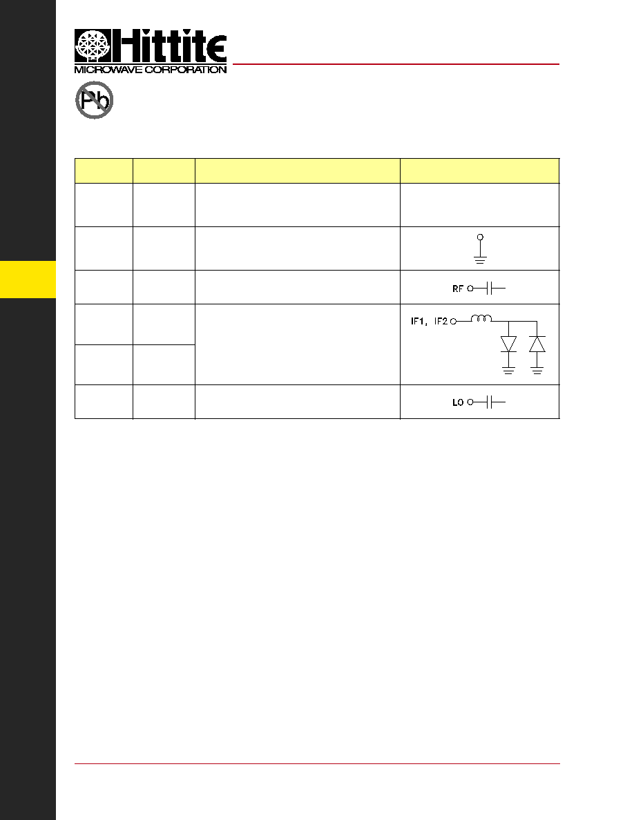
Pin
Number
Function
Description
Interface Schematic
1, 2, 6-8,
10, 13,
17-24
N/C
No connection required. These pins may be connected
to RF/DC ground without affecting performance.
3, 5, 12,
14, 16
GND
These pins and package bottom must be connected
to RF/DC ground.
4
RF
RF Port. This pin is AC coupled and matched to
50 Ohms from 4 to 8.5 GHz.
9
IF1
IF Port. This pin is DC coupled. For applications
not requiring operation to DC, this port should be
DC blocked externally using a series capacitor whose
value has been chosen to pass the necessary IF
frequency range. For operation to DC, this pin must not
source/sink more than 3mA of current or part non-func-
tion and possible part failure will result.
11
IF2
15
LO
LO Port. This pin is AC coupled and matched to
50 Ohms from 4 to 8.5 GHz.
Pin Descriptions
HMC525LC4
GaAs MMIC I/Q MIXER
4 - 8.5 GHz
v00.0105