 | –≠–ª–µ–∫—Ç—Ä–æ–Ω–Ω—ã–π –∫–æ–º–ø–æ–Ω–µ–Ω—Ç: MBF300 | –°–∫–∞—á–∞—Ç—å:  PDF PDF  ZIP ZIP |
Pr
eliminar
y
MBF300
Solid State Fingerprint Sweep SensorTM
Applications
∑ Secure access for databases, networks, local storage
∑ Portable fingerprint acquisition
∑ Smart Cards
∑ Identity verification for ATM transactions
∑ Cellular phone-based security access
∑ Access control and monitoring (home, auto, office, etc.)
Packages
Overview
The Fujitsu MBF300 Solid-State Fingerprint Sweep Sensor is a
direct contact, fingerprint acquisition device. It is a high
performance, low power, low cost, capacitive sensor composed of a
two-dimensional array of metal electrodes in the sensing array.
Each metal electrode acts as one plate of a capacitor and the
contacting finger acts as the second plate. A passivation layer on the
device surface forms the dielectric between these two plates. Ridges
and valleys on the finger yield varying capacitor values across the
array, and the resulting varying discharge voltages are read to form
an image of the fingerprint.
The MBF300 sensor when combined with Sweep Sensor image
capture software works by sliding your finger over the sensor
surface. Rapid image capture software detects muliple fingerprint
images and reconstructs the fingerprint minutia template.
The MBF300 is manufactured in standard CMOS technology.
The 256 X 32 sensor array has a 50 µm pitch and yields a 500-dpi
image. The sensor surface is protected by a patented, ultra-hard,
abrasion and chemical resistant coating.
Features
∑ Capacitive solid-state device
∑ 500-dpi resolution (50 µm pitch)
∑ 1.28 cm x 0.16 cm sensor area
∑ 256 x 32 sensor array
∑ 2.8V to 5V operating range
∑ Exceptionally hard protective coating
∑ Integrated 8-bit analog to digital converter
∑ One of three bus interfaces:
8-bit microprocessor bus interface
Integrated USB Full-Speed Interface
Integrated Serial Peripheral Interface
∑ Standard CMOS technology
∑ Low power, less than 70 mW operating at 5V


Pr
eliminar
y
MBF300
Fujitsu Microelectronics America, Inc.
-1
Table of Contents
Chip Operation .....................................................................................................................................................................1
Block Diagram......................................................................................................................................................................1
Connection Diagram..............................................................................................................................................................2
Pin List................................................................................................................................................................................3
Pin Descriptions....................................................................................................................................................................4
Device Bus Operation.............................................................................................................................................................7
Microprocessor Bus Interface ............................................................................................................................................7
Serial Peripheral Bus Interface (SPI) Slave ................................................................................................................................8
SPI Bus Mode.................................................................................................................................................................8
SPI Slave Mode...............................................................................................................................................................8
Register Read Command in SPI Slave Mode ........................................................................................................................8
Register Write Command for SPI Slave Mode ......................................................................................................................8
USB Interface Mode, Using Internal ROM ................................................................................................................................8
Endpoint 0 ....................................................................................................................................................................8
Endpoint 1 ....................................................................................................................................................................8
Endpoint 2 ....................................................................................................................................................................8
USB Interface Mode, Using External ROM ...............................................................................................................................8
SPI Master Mode ............................................................................................................................................................9
Function Register Descriptions ...............................................................................................................................................9
Function Register Map...........................................................................................................................................................9
RAH 0x00 .....................................................................................................................................................................9
RAL 0x01....................................................................................................................................................................10
CAL 0x02 ....................................................................................................................................................................10
REH 0x03....................................................................................................................................................................10
REL 0x04 ....................................................................................................................................................................10
CEL 0x05 ....................................................................................................................................................................10
DTR 0x06....................................................................................................................................................................11
DCR 0x07....................................................................................................................................................................11
CTRLA 0x08 ...............................................................................................................................................................11
CRTLB 0x09................................................................................................................................................................13
CTRLC 0x0A ...............................................................................................................................................................14
SRA 0x0B....................................................................................................................................................................14
PGC 0x0C ...................................................................................................................................................................15
ICR 0x0D ....................................................................................................................................................................15
ISR 0x0E .....................................................................................................................................................................16
CIDH 0x10 ..................................................................................................................................................................16
Fujitsu Microelectronics America, Inc.

Pr
eliminar
y
Solid State Fingerprint Sweep SensorTM
0
Fujitsu Microelectronics America, Inc.
CIDL 0x11 .................................................................................................................................................................. 16
TST 0x12.................................................................................................................................................................... 16
Sensor Initialization............................................................................................................................................................ 17
Image Retrieval .................................................................................................................................................................. 17
Microprocessor Interface ............................................................................................................................................... 17
Get Row ............................................................................................................................................................... 17
Get Whole Image ................................................................................................................................................... 18
Get Sub-Image ...................................................................................................................................................... 19
Serial Peripheral Interface ...................................................................................................................................... 20
Get Image............................................................................................................................................................. 20
USB Interface........................................................................................................................................................ 21
Get Image............................................................................................................................................................. 21
Absolute Maximum Ratings ................................................................................................................................................. 22
Operating Range ................................................................................................................................................................ 22
DC Characteristics .............................................................................................................................................................. 22
Power Supply Consumption ................................................................................................................................................. 23
AC Characteristics .............................................................................................................................................................. 24
Microprocessor Bus Mode.............................................................................................................................................. 24
Read Cycle ............................................................................................................................................................ 24
Write Cycle ........................................................................................................................................................... 24
SPI Slave Mode...................................................................................................................................................... 25
SPI Master............................................................................................................................................................ 25
Timing Diagrams................................................................................................................................................................ 26
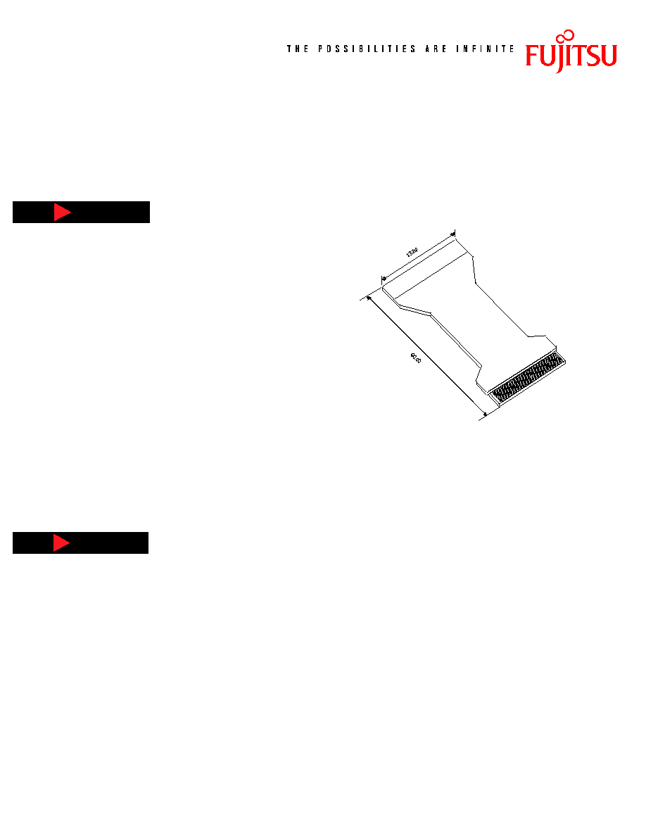
Physical Dimensions............................................................................................................................................................ 30
Array Orientation............................................................................................................................................................... 31
Appendix A ........................................................................................................................................................................ 32
Recommended Power and Ground Connections ................................................................................................................ 32
Fujitsu Microelectronics America, Inc.

Pr
eliminar
y
MBF300
Fujitsu Microelectronics America, Inc.
1
Block Diagram
2 5 6 X 3 2
S E N S O R
A R R A Y
S A M P L E A N D H O L D
F U N C T I O N
R E G I S T E R S
P 0
P 1
D[7:0]
A 0
R D
W R
C S 0
C S 1
M O S I
M I S O
I N T R
D P
D M
T E S T
X T A L 1
X T A L 2
E X T I N T
X T A L
O S C
M U L T I -
V I B R A T O R
INDEX
REGISTER
DATA
REGISTER
A I N
I S E T
F S E T
A N A L O G
S P I
U S B
C O N T R O L
A / D C O N V E R T E R
M O D E 1
M O D E 0
W A I T
Chip Operation
The sensor array includes 256 columns and 32 rows of sensor plates.
Associated with each column are two sample-and-hold circuits.
A fingerprint image is sensed or captured one row at a time. This
"row capture" occurs in two phases. In the first phase, the sensor
plates of the selected row are pre-charged to the VDD voltage.
During this pre-charge period, an internal signal enables the first
set of sample-and-hold circuits to store the pre-charged plate
voltages of the row.
In the second phase, the row of sensor plates is discharged with a
current source. The rate at which a cell is discharged is proportional
to the "discharge current." After a period of time (referred to as
the "discharge time"), an internal signal enables the second set
of sample-and-hold circuits to store the final plate voltages.
The difference between the precharged and discharged plate voltages
is a measure of the capacitance of a sensor cell. After the row capture,
the cells within the row are ready to be digitized.
The sensitivity of the chip is adjusted by changing the discharge
current and discharge time. The nominal value of the current source
is controlled by an external resistor connected between the ISET pin
and ground. The current source is controlled from the Discharge
Current Register (DCR). The discharge time is controlled by the
Discharge Time Register (DTR).