 | –≠–ª–µ–∫—Ç—Ä–æ–Ω–Ω—ã–π –∫–æ–º–ø–æ–Ω–µ–Ω—Ç: EM83812 | –°–∫–∞—á–∞—Ç—å:  PDF PDF  ZIP ZIP |
EM83812
ALL-INONE PLUG & PLAY SCRLLING SERIAL MOUSE CONTROLLER
1
* This specification are subject to be changed without notice.
9.3.1999
Preliminary
Preliminary
Preliminary
Preliminary
Preliminary
GENERAL DESCRIPTION
The EM83812 PnP Scrolling Mouse Controller is specially designed to control serial mouse device.
This single chip can interface three key-switches and 4 X-Y photo-couples plus Z-axis directly to RS-232C.
There are four types Z-axis inputs used to implement scrolling mouse functionality.
FEATURES
∑ Using 50k
±
1% resistor for RC oscillation.
∑ Compatible with Microsoft serial scrolling mouse.
∑ 100 bytes PnP ID code could be filled by code layer.
∑ Built-in noise immunity circuit.
∑ The sampiling rate of motion detector is up to 65KHz.
∑ Built-in three zener diodes : one in VDD to VSS, two in RTS to VDD.
∑ CMOS push-pull RXD output.
∑ Built-in current comparator for photo-couples input.
∑ Built-in three step dynamic input impedance.
∑ Three key-switches and four photo-couples inputs.
∑ RTS debouncing circuit included.
∑ Photo couple test mode included.
∑ Low power dissipation.
∑ Six types Z direction input:
1. Photo couples input. (Z/1)
4. Mechanical input. (Z/1)
2. Key-switches input.
5. Photo couples input. (Z/4)
3. Voltage-sensing input.
6. Mechanical input. (Z/2)
∑ Package type:
EM83812AP : 16DIP, Photo couples input. (Z/1) EM83812DP: 16DIP, Mechanical input. (Z/1)
EM83812BP : 16DIP, Key-switches input.
EM83812EP : 16DIP, Photo couples input. (Z/4)
EM83812CP : 16DIP, Voltage-sensing input.
EM83812FP : 16DIP, Mechanical input. (Z/2)
APPLICATION
∑ Serial PnP scrolling mouse.
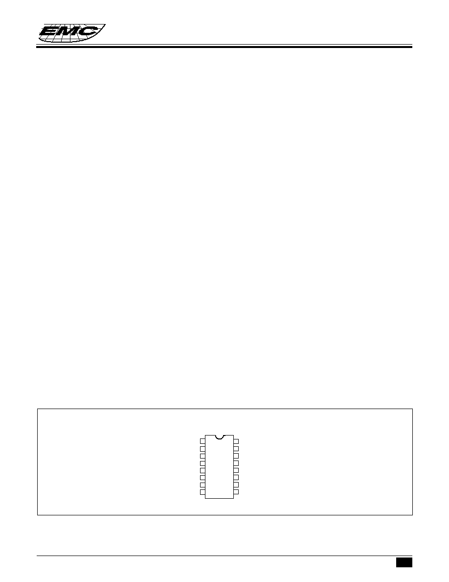
PIN ASSIGNMENT
V
DD
OSC.OUT
Z1
Z2
RTS
RXD
OPT
VSS
1
2
3
4
5
6
7
8
16
15
14
13
12
11
10
9
OSCR
Y2
Y1
X2
X1
L
M
R
EM83812A/B/C/D/E/FP
EM83812
ALL-INONE PLUG & PLAY SCRLLING SERIAL MOUSE CONTROLLER
2
* This specification are subject to be changed without notice.
9.3.1999
Preliminary
Preliminary
Preliminary
Preliminary
Preliminary
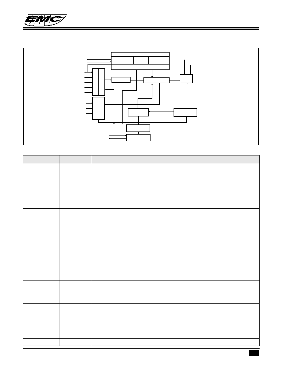
FUNCTIONAL BLOCK DIAGRAM
PIN DESCRIPTIONS
OPT
I/O
INPUT: 200kohm pull low to VSS.
When OPT is connected to VDD, EM84520 will enter test mode. In test mode,
L will be the output of X1,while M will be the output of X2. Toggling R key can
change these output to be Y1,Y2 or Z1,Z2 respectively.
OUTPUT: 2kHz Z-axis LED driving source with A/D/E/F version.
"1"= VDD, "0"= floating
High duty is about 60us.
OSC.OUT
O
The RC oscillation clock output. Or 3mA sink current output for X, Y photo
emitters.
OSCR
I
Connect 50k
±
1% precise resistor for oscillation.
RTS
I/O
±
12V signal with 10mA driving. Used as PnP ID code output trigger signal
from 10w (-12V) to high (+12V) while under normal operating. RTS will keep on
±
12V driving.
RXD
I/O
One report contains 4 data bytes, 7 data bits without parity in the data byte.
The data byte is sgifted out from LSB through MSB, started by start bit and ended
by stop bit. The RXD signal swing between +6V and -6V.
R
I
Three key-switches inputs. 200k
resistor pull low.
M
I/O
In Z-axis key mode, M key toggling can change the scrolling speed from low to
L
I/O
high.
X1
I
Three step dynamic input impedance. If OSC.OUT is not connected to LEDs, the
X2
I
dynamic input impedance will be off.
Y1
I
Use current comparator to measure photo-couples "ON", or "OFF".
Y2
I
Z1
I
Z-axis input.
Z2
I
Photo mode : Three steps dynamic input impedance. Current comparator input.
Key mode : 200 k
resistor pull low. 7 levels increased by "M" key.
Voltage mode : 200 k
resistor pull low. 7 levels voltage comparator.
Mechanical mode : 13.2k
resistor pull low. Current comparator input.
VSS
Negative power.
VDD
Power line.
Symbol
I/O
Function
Z1
Z2
OPT
X1
X2
Y1
Y2
L
M
R
OSCR
OSC.OUT
C
O
M
P
A
R
A
T
O
R
M
O
T
I
O
N
D
E
T
E
C
T
O
R
D
E
B
O
U
N
C
E
COUNTER
COMMAND
STATUS
SYSTEM CLOCK
GENERATOR
RC
OSCILLATION
MULTIPLEXER
DATA
I/O
TIMING
CONTROLLER
COMPARATOR VOLTAGE
SENSOR
KEY-SWITCH
DETECTOR
Z-AXIS COUNTER
THREE TYPES SELECTOR
RXD
RTS

EM83812
ALL-INONE PLUG & PLAY SCRLLING SERIAL MOUSE CONTROLLER
3
* This specification are subject to be changed without notice.
9.3.1999
Preliminary
Preliminary
Preliminary
Preliminary
Preliminary
FUNCTION DESCRIPTIONS
(I) Serial Scrolling Mouse :
In Microsoft mode, the transmission cycle consists of four bytes in one report. Each byte contains one start
bit, 7 data bits and two stop bits. The first byte contains "L", "R" key status and four bits of the two most
significant bits in horizontal counter and vertical counter. The second byte represents the value accumulated
by horizontal counter, the third byte is the data of the vertical counter. The last byte contains "M" key status
and Z-axis value. The vertical data is transmitted in 2's complement.
Output byte arrange
Bit no.
......
6
5
4
3
2
1
0
1st byte
......
1
L
R
V7'
V6'
H7
H6
2nd byte
....
0
H5
H4
H3
H2
H1
H0
3rd byte
....
0
V5'
V4'
V3'
V2'
V1'
V0'
4th byte
....
0
0
M
Z3
Z2
Z1
Z0
Plug & Play ID code
When RTS input from low to high, EM84520 will send a string ID code. Customer can specify the contains
of the code area and the total lenth below 100 bytes by changing the code layer.
Field Name
Length
Field Data
Description
Other ID
<17
4D, 5A, 40, 00, 00, 00
ID for legacy
Begin ID
1
08
Begin PnP ID
PnP Revision
2
01, 24
Version 1.00
EISA ID
3
25, 2D, 23
EMC
Product ID
4
10, 10, 10, 11
0001
Serial Number
9
3C
None provided
Class ID
<34
3C, 2D, 2F, 35, 33, 25
Mouse Class
Driver ID
<42
3C, 30, 2E, 30, 10 26, 10, 21
PnP0F0A
User Name
<42
3C, 25, 2D, 23, 00, 33, 23, 32,
EMC SCROLLING
2F, 2C, 2C, 29, 2E, 27, 00, 33,
SERIAL MOUSE
25, 32, 29, 21, 2C, 00, 2D, 2F,
35, 33, 25
Check sum
2
21, 15
2 bytes checks um
End PnP
1
09
End PnP ID
(II). Z-axis Input Function :
(a) Photo couples input : Z-axis counter accumulates the Z1, Z2 phase changed by movement.
(b) Key-switches input : Pressing Z1, Z2 will start to fill the Z-axis counter with the value beginning at one.
Toggling "M" key can increase the value any time by one. The limit value is
±
7.
(c) The relationship between the value and the transmission rate as follows :

EM83812
ALL-INONE PLUG & PLAY SCRLLING SERIAL MOUSE CONTROLLER
4
* This specification are subject to be changed without notice.
9.3.1999
Preliminary
Preliminary
Preliminary
Preliminary
Preliminary
Value
Rate per second
1
2.7
2
6.4
3
9.2
4
12.8
5
15
6
18
7
20
(d) Voltage-sensing mode : There are 7 voltage levels in Z1, Z2 input. The transmission table is the same as
key-switches mode. The relationship between the value of Z-axis counter and the voltage as folllows :
Value
Voltage
0
1V
1
1.0V-1.6V
2
1.6V-2.2V
3
2.2V-2.8V
4
2.8V-3.4V
5
3.4V-4.0V
6
4.0V-4.6V
7
4.6V
Under V
DD
=5V condition.
(e) Mechanical mode : The same as optical wheel mode.

EM83812
ALL-INONE PLUG & PLAY SCRLLING SERIAL MOUSE CONTROLLER
5
* This specification are subject to be changed without notice.
9.3.1999
Preliminary
Preliminary
Preliminary
Preliminary
Preliminary
Operating voltage
Vdd
4.5
6
6.5
V
Vrts
-
12
13
V
Operating current
Iop1
-
-
0.8
mA
(Vdd=5.4, RTS=Vdd)
Operating current
Iop2
3
-
-
mA
(Vdd=6.2, RTS=Vdd)
RTS Operating current
Irts1
-
-
1.8
mA
(Vdd=5.6, RTS=11V)
RTS operating current
(Vdd=5.6, RTS=12V)
Irts2
4
-
-
mA
RXD high output voltage
Irh
2
-
-
mA
(Vrh=Vrts=2.6V)
RXD low output voltage
Irl
-
-
-2
mA
(Vrh=Vss+2.6V)
RTS high input voltage
Vrts+
9.6
-
-
V
RTS low input voltage
Vrts-
-
-
6.8
V
X1,X2,Y1,Y2,Z1,Z2 (photo mode)
Ipl
70
-
-
µ
A
low input reference current
X1,X2,Y1,Y2,Z1,Z2 (photo mode)
Iph
-
-
106
µ
A
high input reference current
X1,X2,Y1,Y2,Z1,Z2 (photo mode)
Vpl1
0.8
-
1.2
V
input current
(input impedance) (80
µ
A)
X1,X2,Y1,Y2,Z1,Z2 (photo mode)
Vpl2
1.5
-
2.1
V
input current
(input impedance) (500
µ
A)
L,M,R,OPT,Z1,Z2 (key mode)
Vail
-
-
1.5
V
input low voltage
Z1,Z2 (key mode)
Vaih
3.5
-
-
V
input high voltage
Z1,Z2 (voltage mode)
Vs
-0.3
-
+0.3
V
sensitivity
L,M,R,Z1,Z2 (key & voltage mode)
Imi
18
-
56
µ
A
input current
(Vds=5.6V)
OPT
Ixi
-18
-
-56
µ
A
input current
OPT
Idc
4.5
-
-
V
high output current
(Iopt=20mA)
L,M,R,X1,X2,Y1,Y2,Z1,Z2
Iil
0
-
-1.0
µ
A
input leakage current
(Vds=0V)
OPT
Iih
0
-
1.0
µ
A
input leakage current
(Vds=5.6V)
DC ELECTRICAL CHARACTERISTICS (T
A
=25
∞
C to 70
∞
C, Vds=5.6V))
Parameters
Sym.
Min.
Typ.
Max.
Unit
ABSOLUTE MAXIMUM RATINGS
Parameter
Ratings
Unit
Min.
Max.
Temperature under bias
0
70
∞
C
Storage temperature range
-65
150
∞
C
Supply voltage
-0.3
7.5
V
Power dissipation
-
500
mW
* All voltage in above table are compared with VSS.