 | –≠–ª–µ–∫—Ç—Ä–æ–Ω–Ω—ã–π –∫–æ–º–ø–æ–Ω–µ–Ω—Ç: ELM382DSA | –°–∫–∞—á–∞—Ç—å:  PDF PDF  ZIP ZIP |

ELM382
Elm Electronics ≠ Circuits for the Hobbyist
< http://www.elmelectronics.com/ >
Connection Diagram
PDIP and SOIC
(top view)
V
DD
V
SS
1
2
3
4
8
7
6
5
The ELM382 is a digitally configurable, multi-
stage counter circuit in a single 8 pin package. When
connected to a 50Hz source, four time periods from
one hour to one week are possible, as shown in
Table 1 below.
Although the circuit has been optimized for a
50Hz input frequency, it is capable of being operated
over a very wide range of frequencies. Of particular
interest is the ability to interface directly to very low
frequencies with varying waveforms due to the use
of a Schmitt trigger input circuit.
The ELM382 provides two outputs ≠ a standard
50% duty cycle divider output, and a momentarily
pulsed output. The pulse output is useful for audibly
or visually signalling the beginning of a time period,
or as a trigger for other circuitry. Refer to the
Example Applications section for two typical circuits.
Out
Description
∑ Long term (daily or weekly) event timers
∑ Missing event detectors
∑ Automatic shutoff circuits
Applications
Block Diagram
1 of 4
∑ Low power CMOS design - typically 1mA at 5V
∑ Wide supply range ≠ 3.0 to 5.5 volt operation
∑ Digitally selectable delays
∑ Schmitt trigger circuitry on the clock input
∑ Completely static operation
∑ Long term accuracy with line frequency clock
∑ High current drive outputs ≠ up to 25 mA
∑ Reset input provided with a pullup resistor
Features
ELM382DSA
Clock
reset
50 Hz Long Interval Counter
Pulse
D1
D0
5
Clock
7
Out
4
6
Digital
Counters
2
V
DD
reset
D1
Pulse
Generator
Pulse
D0
3
V
DD
V
SS
Table 1
(50Hz)
7 days
12 hrs
1 hour
24 hrs
D1
L
H
H
L
D0
H
H
L
L
Setting
Divisor
2160
180
30,240
4320
x 1000
Period

ELM382
Elm Electronics ≠ Circuits for the Hobbyist
< http://www.elmelectronics.com/ >
Pin Descriptions
Ordering Information
These integrated circuits are available in either the 300 mil plastic DIP format, or in the 200 mil SOIC surface
mount type of package. To order, add the appropriate suffix to the part number:
300 mil Plastic DIP............................... ELM382P
200 mil SOIC..................................... ELM382SM
2 of 4
All rights reserved. Copyright ©2000 Elm Electronics.
Every effort is made to verify the accuracy of information provided in this document, but no representation or warranty can be
given and no liability assumed by Elm Electronics with respect to the accuracy and/or use of any products or information
described in this document. Elm Electronics will not be responsible for any patent infringements arising from the use of these
products or information, and does not authorize or warrant the use of any Elm Electronics product in life support devices and/or
systems. Elm Electronics reserves the right to make changes to the device(s) described in this document in order to improve
reliability, function, or design.
V
DD
(pin 1)
This pin is the positive supply pin, and should
always be the most positive point in the circuit.
Internal circuitry connected to this pin is used to
provide power on reset of the microprocessor, so
an external reset signal is normally not required.
Refer to the Electrical Characteristics section for
further information.
D1 (pin 2) and D0 (pin 3)
The logic levels on these pins control the divider
ratio, as shown in Table 1. Their levels are stored
in an internal latch on the low to high transistion of
the Pulse output, and are used for that entire
timing period.
reset (pin 4)
An active low input that forces both outputs low,
and causes all counter stages to initialize. If
unused, it can be left open circuited (due to the
internal resistor) or preferrably tied to V
DD
. Refer to
the minimum timing requirements in the Electrical
Characteristics section.
Clock (pin 5)
The counter stages advance on the falling edge
(V
DD
to V
SS
) of this input, if there is no reset signal
present. The Schmitt trigger amplifier on the
input simplifies the coupling to slowly varying
signals, while the inherent protection diodes
(shown in the block diagram) allow signals with
peak levels beyond the supply limits to be
connected through a current limiting resistor.
Pulse (pin 6)
This output pin is normally at a low level, but is
momentarily driven high at the beginning of
every timing period. The duration of the pulse is
fixed at 50 cycles of the clock input (nominally 1
second with a 50Hz input). This output will not
assume a high level following a circuit reset until
there has been a valid clock transition.
Out (pin 7)
This is the main timing chain output. It has a
fixed 50% duty cycle, and begins each timing
cycle at a logic low level. Halfway through each
cycle, Out will assume a logic high level and will
remain high until the end of the timing period.
V
SS
(pin 8)
Circuit common is connected to this pin. This is
the most negative point in the circuit.
ELM382DSA

Elm Electronics ≠ Circuits for the Hobbyist
< http://www.elmelectronics.com/ >
ELM382
Electrical Characteristics
Absolute Maximum Ratings
Storage Temperature....................... -65∞C to +150∞C
Ambient Temperature with
Power Applied....................................-40∞C to +85∞C
Voltage on V
DD
with respect to V
SS
............ 0 to +7.5V
Voltage on any other pin with
respect to V
SS
........................... -0.6V to (V
DD
+ 0.6V)
Note:
Stresses beyond those listed here will likely damage
the device. These values are given as a design
guideline only. The ability to operate to these levels
is neither inferred nor recommended.
3 of 4
All values are for operation at 25∞C and a 5V supply, unless otherwise noted. For further information, refer to note 1 below.
Characteristic
Minimum
Typical
Maximum
Conditions
Units
Supply Voltage, V
DD
3.0
5.0
5.5
V
V
DD
rate of rise
0.05
V/ms
Average Supply Current, I
DD
1.0
2.4
mA
V
DD
= 5V
Notes:
1. This integrated circuit is produced with a Microchip Technology Inc.'s PIC12C5XX as the core embedded
microcontroller. For further device specifications, and possibly clarification of those given, please refer to the
appropriate Microchip documentation.
2. This specification must be met in order to ensure that a correct power on reset occurs. It is quite easily
achieved using most common types of supplies, but may be violated if one uses a slowly varying supply
voltage, as may be obtained through direct connection to solar cells, or some charge pump circuits.
3. The value of the internal pullup resistance is both supply and temperature dependent.
4. This refers to the current flowing through the protection diodes when large voltages are applied to the clock
input (pin 5) through a current limiting resistance. Currents quoted are the maximum continuous.
Input low voltage
V
SS
0.15 V
DD
V
Input high voltage
V
DD
V
0.85 V
DD
Output low voltage
0.6
V
Output high voltage
V
V
DD
- 0.7
Current (sink) = 8.7mA
Current (source) = 5.4mA
Internal pullup resistance
300
500
600
K
Pin 4 (reset) ≠ see note 3
see note 2
ELM382DSA
Operating Frequency
Hz
50
Input current
-0.5
+0.5
mA
Clock input only ≠ see note 4
0
10K
Reset Pulse Width
10
µs
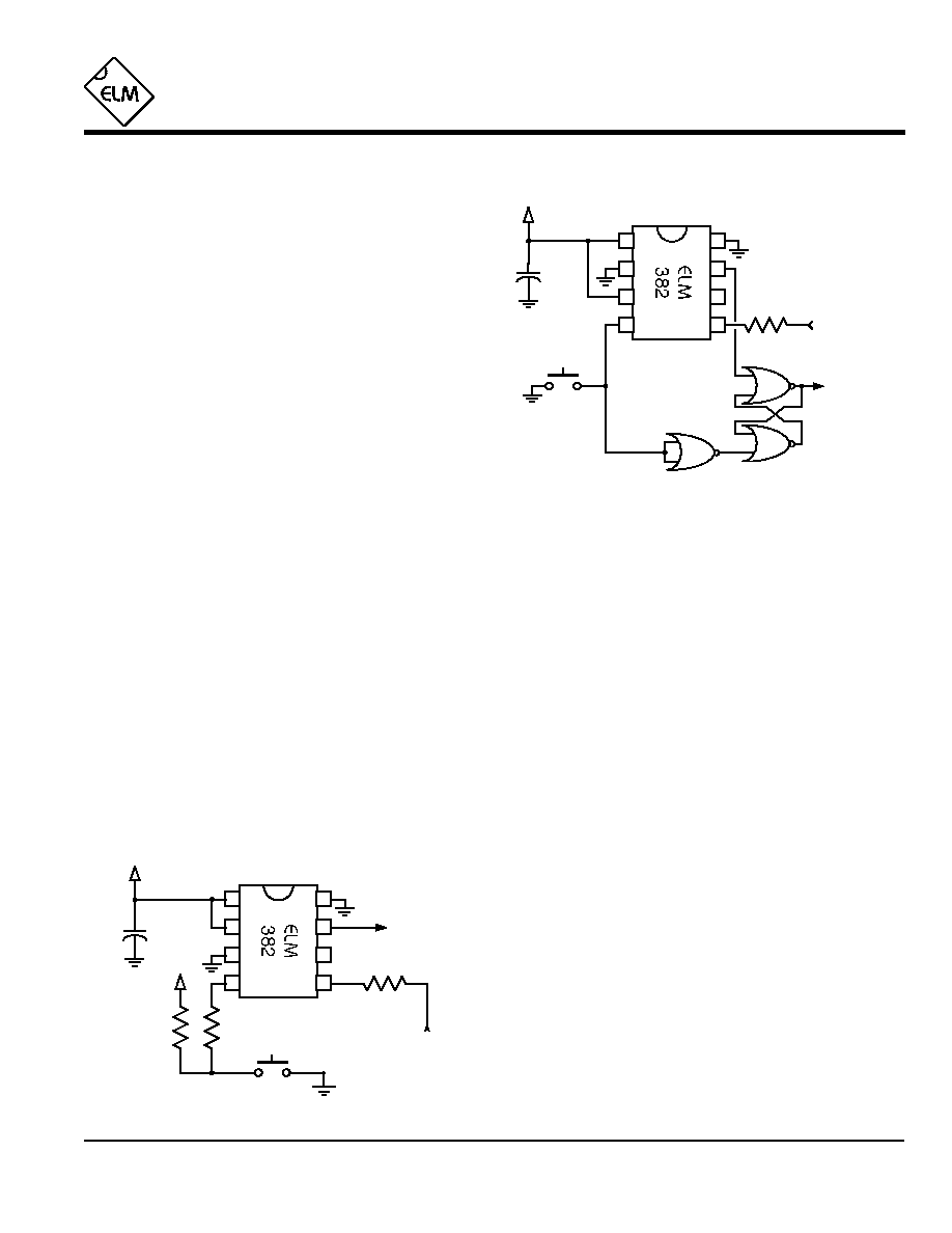
Example Applications
4 of 4
The following shows two circuits using the ELM382.
In both cases, it is assumed that the 50Hz for the clock
input has been derived from another circuit, with due
regard for the safety of the users. Isolating/stepdown
transformers should be used whenever possible.
Typically, a sinusoidal AC voltage will be used for
the clock signal, with a peak magnitude that is greater
than V
DD
(or less than V
SS
). For these cases, a series
resistor (100K
in the figures) must be added to prevent
the input currents from exceeding the protection diode
capabilities. Another design consideration is the need to
provide a DC path from the Clock input back to either
V
DD
or V
SS
at all times (so the CMOS input is not left
floating). As an example, connecting to one side of a
centre-tapped transformer that has its centre connected
to V
SS
is an excellent way to obtain a signal, while
maintaining a DC path to V
SS
through the winding. No
extra resistor is needed in this case. Connecting to the
`DC side' of a half wave rectifier circuit is likely not
advisable however, without adding an extra pulldown
resistor to ensure that the voltage returns to Vss when
the clock signal is not present. (Recall that a reverse
biased diode is essentially an open circuit.)
The first example (Figure 1) is designed to control a
swimming pool pump. This circuit is useful for stopping
the circulating pump during the night (reducing energy
consumption and heat loss), while providing normal
operation during the day. The interface to the high
voltage pump supply is not shown, but would typically
be a transistor stage driving an electromechanical relay
circuit.
The pushbutton shown is pressed once on the first
day at about 7pm, resetting the circuit. With D1=H and
D0=L, the circuit will then operate continuously with a
24 hour period, the output (Pump Enable) at a high level
from 7am to 7pm, and at a low level otherwise.
The two resistors shown with asterisks (*) may be
required to reduce the effects of induced charges and
currents if the pushbutton is mounted more than a
couple of feet from the IC. In this case, protecting
resistors (typically about 10K
) should be connected as
shown.
Figure 2 shows another typical circuit. This one is a
retriggerable timer that could be used to control lights,
fans, etc. while providing an `auto-off' feature. For the
circuit shown, the control output remains active for a
minimum of six hours, but the period is extended each
time the start button is pressed.
The ELM382 is inherently an astable circuit that
cycles on and off continually, so using it for this
`retriggerable one-shot' operation requires the addition
of external latching circuitry as shown. A quad NOR
(CMOS 4001) provides the required logic while leaving
a fourth gate free for other uses (be sure to tie its inputs
to V
DD
or V
SS
if unused).
In operation, a new timing period begins whenever
the pushbutton is pressed, as it is tied to the reset input.
The Control Output latch is also set by this action,
forcing a high output. If a half period is ever reached
the ELM382 Out signal (pin 7) will go high, resetting the
latch and causing a low Control Output. After this time,
the ELM382 will continue to cycle, but the Contol Output
will remain off. As with the circuit of Figure 1,
precautions should be taken if the pushbutton is located
in an electrically noisy environment, or an appreciable
distance from the integrated circuit.
As shown by these two examples, the ELM382
simplifies many long term timing applications, allowing
several new possibilities...
ELM382
ELM382DSA
Elm Electronics ≠ Circuits for the Hobbyist
< http://www.elmelectronics.com/ >
Figure 1. Pool Pump Control Circuit
1
2
3
4
8
7
6
5
time zero
50Hz
Input
*
Pump
Enable
100K
+5V
+5V
*
0.01µF
1
2
3
4
8
7
6
5
start
50Hz
Input
Control
Output
100K
+5V
0.01µF
Figure 2. Retriggerable Control Circuit