 | –≠–ª–µ–∫—Ç—Ä–æ–Ω–Ω—ã–π –∫–æ–º–ø–æ–Ω–µ–Ω—Ç: MA3690 | –°–∫–∞—á–∞—Ç—å:  PDF PDF  ZIP ZIP |

MA3690/1/3
1/41
The MA3690/1 chip set has three modes of operation:
remote terminal, bus controller, and passive monitor It has a
dual bus capability, requires minimum support hardware /
software and is implemented on a radiation hard, CMOS/SOS
process. For applications requiring access to Terminal Flag, a
48-Pin DIL MA3693 is available as an alternative to the
MA3690.
As a remote terminal, the MA3690/1 is fully compatible with
Mil-Std-1553B. The chip set obtained SEAFAC approval in
December 1987. All options and mode commands specified by
the Mil Std are implemented Full and meaningful use is made
of status word bits and a comprehensive bit word is provided.
A unique mechanism has been incorporated that allows
the subsystem to declare illegal commands legal, and vice
versa, before the chip set services the command. It should be
noted that use of this mechanism is optional and that the
system defaults to normal operation if the option is not
required. The chip set is easily interfaced to subsystem
memory and is sufficiently flexible to ensure compatibility with
a wide range of microprocessors.
As a bus controller the MA3690/1 has the ability to initiate
all types of 1553B transfer on either of the two buses An
instruction word is set up by the subsystem, prior to
transmission, which contains details of transfer type and bus
selection. Four bits of the instruction word have been used to
specify the conditions under which the chip set will generate a
subsystem interrupt. The most significant bits of the instruction
word have been used to specify the conditions under which the
chip set will perform an automatic retry and the number of
retries to be carried out (max. 3). At the end of each instruction
execution cycle, the chip set writes a report word into the
subsystem memory; the contents of which give the subsystem
an indication of the degree of success of the transfer.
The bus controller may be used in either of two
configurations, i.e. single shot or table driven.
In the single shot configuration, the controller is under
direct control from the subsystem (processor). In table driven
configuration, the controller is given greater autonomy to
execute a table of instructions held in either ROM or RAM.
As a passive monitor, the chip set will monitor all bus
activity and pass any associated information to the subsystem.
As the name implies, in this mode of operation, the chip set is
truly passive and will not reply to command instructions.
FEATURES
s
Radiation Hard to 1MRads (Si)
s
High SEU Immunity, Latch-Up Free
s
CMOS-SOS Technology
s
All Inputs and Outputs Fully TTL or CMOS Compatible
s
Military Temperature Range -55 to +125
∞
C
s
Dual Bus Capability
s
Minimal Subsystem Interface
s
Powerful Bus Control Facility
s
Complete Remote Terminal Protocol
s
SEAFAC Approved
SIGNAL DESCRIPTIONS
All signals are TTL compatible unless stated otherwise. An
`N' at the end of the signal name denotes an active low signal.
SUPPLIES
VDD
5 volts positive supply
VSS
Ground
CLOCK INPUTS
CK12
12MHz clock
BUS INTERFACE LINES
PDIN0
Input
Positive threshold exceeded on bus 0.
NDIN0
Input
Negative threshold exceeded on bus 0.
TXEN0N
Output
Transmit enable for driver on bus 0.
PDOUT0N
Output
Positive Manchester data for driver on bus 0.
MA3690/1/3
1553B Bus Controller/Remote Terminal
Replaces June 1999 version, DS3587-4.0
DS3587-5.0 January 2000

MA3690/1/3
2/41
NDOUT0N
Output
Negative Manchester data for driver on bus 0.
PDIN1
Input
Positive threshold exceeded on bus 1.
NDIN1
Input
Negative threshold exceeded on bus 1.
TXEN1N
Output
Transmit enable for driver on bus 1.
PDOUT1N
Output
Positive Manchester data for driver on bus 1.
NDOUT1N
Output
Negative Manchester data for driver on bus 1.
SUBSYSTEM INTERFACE LINES
STROBEN
Output
STROBE - Information transfer strobe pulse for words being
transferred on the data highway.
BUFENN
Output
BUFFER ENABLE - This line goes low to enable the data
highway buffer between the terminal and the subsystem.
R/WN
Output
READ/WRITE - This line indicates the direction of information
transfer between the terminal and the subsystem. When low,
information is being written from the terminal to the
subsystem.
DTRQN
Output
DATA TRANSFER REQUEST - This line goes low to request
permission to transfer a non mode data word to or from the
subsystem.
DTAKN
Input
DATA TRANSFER ACKNOWLEDGE - This line should be
driven low to grant permission to perform the requested data
word transfer.
MDTN
Output
MODE DATA TRANSFER -
RT: This line goes low to indicate that the data word being
transferred is assosiated with a mode command.
BC: When operating as a passive monitor this line goes low
to indicate that a valid data word is on the data highway and
should be written into the received data latch.
GBRN
Output
GOOD BLOCK RECEIVED - When in RT mode this line will
pulse low to inform the subsystem that the received non
mode data words are valid and may be used.
ADENN
Output
ADDRESS ENABLE - When in RT mode this line will go low
as part of the reset routine to enable the terminal address on
to the data highway.
SYNCN
Output
SYNCHRONISE - This line will pulse low if a valid
synchronise mode command without data is received and
passes all validity checks.
STATENN
Output
STATUS ENABLE -
RT: When low this line enables the contents of the
subsystem status latch on to the data highway.
BC: When low this line enables the BC report word on to the
data highway.
MDRN
Output
MODE DATA RECEIVED - This line will pulse low to
inform the subsystem that the received mode data is
valid and may be used.
RXCMDN
Output
RECEIVED COMMAND -
RT: This line goes low to indicate that a valid command word
for this RT is on the highway and should be written into the
command word latch.
BC: When operating as a passive monitor this line goes low
to indicate that a valid command / status word is on the data
highway and should be written into the received status latch.
BUSYREQN / HALTREQN Input
BUSY REQUEST / HALT REQUEST -
RT: This line should be driven low as a request for the
terminal to set the busy bit and inhibit non mode data
transfers to or from the subsystem.
BC: This line should be driven low as a request for the
terminal to halt table execution and all subsystem access.
BUSYACKN / HALTEDN
Output
BUSY ACKNOWLEDGE / HALTED -
RT: This line will go low to indicate that the subsystem has
free access to the shared store.
BC: This line will go low to indicate that all terminal operation
has been halted and hence the subsystem has free access to
the shared store.
CODENN
Output
CODE ENABLE - This line when low indicates that a
word transfer between the terminal and either the
Instruction Store or the Report Store is taking place.
C0
Output
CODE 0 - This line is the least significant address line from
the terminal to the Instruction and Report Stores.
C1
Output
CODE 1 - This line is the least significant but one address
line from the terminal to the Instruction and Report Stores.

MA3690/1/3
3/41
INCADRN
Output
INCREMENT ADDRESS - This line pulses low to increment
the external instruction addressing counter.
HSFN/IRQN Output
HANDSHAKE FAIL / INTERRUPT REQUEST
RT: This line pulses low to inform the subsystem that it has
not responded to a data transfer request to take place.
BC: This line pulses low to generate an interrupt to the BC
subsystem processor.
INCMDN
Output
IN COMMAND - When low this line indicates that the terminal
is currently servicing a command word.
EOTN
Output
END OF TRANSMISSION - When low this line indicates that
the selected bus is quiet and hence available for use.
ABORTN
Output
This line will pulse low to abort execution of the current
command if an error is detected.
B0-B15
Input/Output
HIGHWAY LINES - 16 line bidirectional Output data highway.
(B0 = LSB).
CLDN
Inter-chip (CMOS)
COMMAND LOAD - When low this line indicates that the
word on the data highway should be loaded into the
transmitter for transmission with a command sync.
DLDN
Inter-chip (CMOS)
DATA LOAD - When low this line indicates that the word on
the data highway should be loaded into the transmitter for
transmission with a data sync.
OBFN
Inter-chip (CMOS)
OUTPUT BUFFER FULL - When low this line indicates that
the transmitter output buffer is full and cannot be overwritten.
VALDRN
Inter-chip (CMOS)
VALID DATA RECEIVED - When low this line indicates that a
valid data word has been received and is on the data
highway.
VALCRN
Inter-chip (CMOS)
VALID COMMAND RECEIVED -
RT: When low this line indicates that a valid command word
for this RT has been received.
BC: When low this line indicates that a valid word with a
command sync has been received.
RT/BCN
Input
REMOTE TERMINAL/BUS CONTROLLER - When high the
terminal will function as an RT.When low the terminal will
function as a bus controller.
CK4
Output
4MHz system clock.
PUCN
Input
POWER UP CLEAR - This line should be pulsed low
following power-up.
RESETN
Input/Output
RESET - This line when low, forces the internal circuitry to
reset to the quiescent initialised state. This is a `TTL' level
input on both devices and an open-drain output on the
MA3690. The subsystem should drive this line via an open
drain/collector device with external pull up fitted.
RT0 / RT1
Inputs
REPLY TIMEOUT DECODE - These lines on the MA3690
allow four different timeout values to be used. On the
MA3693, the RT1 signal is not available and is pulled down
internally.
RT1
RT0
Timeout (us)
0
0
16
0
1
22
1
0
44
1
1
108
Note: Under normal operation, option 00 should be used.
(i.e. 16uS)
The measurement is taken between mid parity and mid sync
- measured at PDIN/NDIN terminals.
TF
Output
TERMINAL FLAG - This line is available only on the 64-pin
MA3690 and on the MA3693 (where it replaces RT1). The
line indicates the state of the Terminal Flag bit in the Status
Word, and can be inhibited by the mode code Inhibit
Terminal Flag. This is an active LOW signal.
TEST/SOT
Inputs
These lines are for test purposes only and for normal chip set
operation must both be tied low.

MA3690/1/3
4/41
OPERATION IN BUS CONTROL MODE
For this mode of operation the RT/BC pin must be held in
the logic zero state. On power up the PUC or RESET line must
be pulsed low for a minimum of 500ns causing the chip set to
initialise and assume the halted state with the HALTED output
low. To release the terminal from the halted state, the
subsystem must drive the HALTREQ line through a low to high
transition, at which time the HALTED line will go inactive.
When the HALTED line goes inactive,the terminal will
address a four word deep Instruction Store as shown below,
using the C0 and Cl outputs.
This first instruction after a Reset is a NOOP.
INSTRUCTION STORE
C1
C0
Word
0
0
Instruction
0
1
Receive Command
1
0
Transmit Command
1
1
Data Pointer
The instruction word specifies the operation which the
terminal is to carry out, and is formatted in the following way:
Instruction Word
Bit
15.14. 13.12.11. 10.9.8.7.
6.5.
4.3.
2.1.0.
Retry
Retry
Interrupt
Bus
Functlon Message
Count Condition Conditlon
Select Code
Code
The significance of the instruction word bits are as follows:
Message Code
Code
Transfer Type
000
RT to BC
001
BC to RT
010
RT to RT, data to BC subsystem
011
RT to RT, no data to BC subsystem
100
Broadcast RT to BC, non data mode commands only
101
Broadcast BC to RT
110
Broadcast RT to RT, data to BC subsystem
111
Broadcast RT to RT, no data to BC subsystem
Mode Codes without data are followed by a NOOP.
Function Code
Code
Terminal Function
00
Execute message code
01
Perform self test
10
Monitor bus
11
No operation (NOOP)
The Function Code (bits 4 and 3 of the Instruction Word)
specifies the required terminal mode of operation.
Execute - Code 00
With the Function code bits set to 00, the terminal will
execute the message as defined in the Message code bits
Self Test - Code 01
If the terminal has been selected to perform a Self Test
then the terminal transmitter output stages will be disabled and
the self test sequence entered. At the end of the Self Test the
transmitter stages will be re-enabled and a Report sequence
will be activated, in order to report on the success, or failure, of
the Self Test.
Passive Monitor - Code 10
If the Function code of the Instruction word is 10 the
terminal will disable the transmitter output stages, suspend
table execution and merely monitor the specified bus for valid
words.
No Operation - Code 11
The No Operation code provides a means of introducing
delay or a wait sequence into the table operation. In selecting
this code the terminal will be forced into the Report sequence
and provide either an increment signal (INCADRN) or an
interrupt (IRQN) if the Interrupt Always flag in the Instruction
word has been selected.
Bus Select
Code
Definition
00
Transmit on bus 0
01
Transmit on bus 1
Note: Bit 6 of the instruction word is tied low internally.
The required data bus on which transactions take place is
defined by bit 5. In addition to this, this bit defines the bus on
which the Transmitter Self Test operation will be conducted
and the choice of the bus for monitor purposes in Passive
Monitor mode.
Interrupt Condition
Code
Definition
0001
Interrupt if no response
0010
Interrupt if status bit set
0100
Interrupt always
1000
Interrupt if word error
If the terminal detects one of the above conditions and the
appropriate flag is set, the the IRQ line will pulse low for 250ns.

MA3690/1/3
5/41
Four bits of the Instruction word (bits 10-7) define
conditions under which the terminal will generate an interrupt
to the subsystem (IRQN). Note that the generation of IRQN will
only take place after any selected retry conditions have been
exhausted.
The interrupt conditions which may be selected can be
categorised as follows:
1. Interrupt if no response - the terminal will generate an
interrupt if the RT does not respond.
2. Interrupt if Status bit set - the terminal will generate an
interrupt if a received status word has a bit set other
than in the RT address field or if the wrong RT
responds.
3. Interrupt Always - the terminal will generate an
interrupt regardless of whether the message was
successful or not.
4. Interrupt if word error - the terminal will generate an
interrupt if a word encoding or word count error
occurs.
In all of the above cases, the terminal will generate a 250ns
pulse on IRQN and enter the halted state. This will occur after
the Report sequence has been executed.
Note the INCADRN will not be produced.
Retry Condition
Code
Definition
001
Retry if error
010
Retry if status bit set
100
Retry if busy set
Three bits of the Instruction word (bits 13-11) are used as
flags to specify conditions under which the terminal will
execute automatic message retries until the retry number
count is zero. The retry flags are involved with the following
conditions:
1. Retry if error - this includes a no-status response, a
word encoding error, or a wrong word count from a
responding RT.
2. Retry if Status bit set - an automatic retry will take
place if a received status word has a bit set, other
than in the RT address field, or if the wrong RT
responds.
3. Retry if Busy - this is a specific check for the setting of
the Busy bit in a responding RT's status word.
The remaining two bits of the Instruction word specify the
number of message retries which the Bus Controller will
attempt automatically. A code of 00 specifies no retries, a code
of 11 specifies the maximum of three retries. The retries are in
addition to the initial message transmitted, hence a message
may be transmitted four times in total, if not successful. Note
that if the condition which is being tested becomes invalid, the
retry sequence will discontinue on the next message with the
Bus Controller completing execution of the message in the
relevant manner.
Retry Count
The two most significant bits of the instruction word specify
the number of retries to be carried out when a retry condition
has been detected. (Maximun 3 given by code 11)
RECEIVE COMMAND WORD
The receive command word is addressed when CODENN
and C1 are both low and R/WN and C0 are both high. This
word is the command word which will be transmitted for a BC
to RT transfer or as the first command word of an RT to RT
transfer.
Note: This word should be set to 1111 HEX if the message
code is 000 or 100, or if the Function Code is not 00.
TRANSMIT COMMAND WORD
The transmit command word is addressed when CODENN
and C0 are both low and R/WN and C1 are both high. This
word is the command word which will be transmitted for an RT
to BC transfer or as the second command word of an RT to RT
transfer.
Note: This word should be set to 1111 HEX if the message
code is 001 or 101, or if the Function Code is not 00.
DATA POINTER WORD
The data pointer word is addressed when CODENN is low
and C0, C1 and R/WN are all high. This word is intended as a
base address pointer to the subsystem data store thus
specifying where any data words associated with the current
instruction should be stored or retrieved from. As such, this
word is not read into the terminal itself but is merely transferred
from the Instruction Store to a suitable external address latch.
(The BUFENN signal is therefore inactive during this transfer).

MA3690/1/3
6/41
REPORT STORE
The report store holds information concerning the success
or failure of the execution of the last instruction, and is
addressed by means of the CODENN, C0 and C1 lines as for
the instruction store The report store is addressed when the R/
WN line is low, the instruction store when the R/WN line is
high.
The report store comprises a Report word, a receive status
word (if applicable) and a transmit status word (if applicable).
The fourth location has no meaning and is not at anytime
addressed.
C1
C0
Word
0
0
Report word
0
1
RX status word
1
0
TX status word
1
1
Not used
REPORT WORD
The report word gives the subsystem information as to the
type of error associated with the last transfer (the word will be
clear if no error occurred). The report word is formatted as
follows:
The Report word is written at the end of message
execution, after all retries have been exhausted and prior to
the IRQN line being set active This word indicates the health of
the terminal as well as information relating to the message
execution.
Transmitter Timeout Error
This bit will be set if a transmitter timeout error occurs while
the terminal is transmittting or if a self test on the transmitter
timeout mechanism fails. This will come into effect 800us after
the commencement of the Self Test. The setting of this bit will
also cause a subsystem interrupt to be generated.
This bit will be reset to logic zero if the terminal is reset.
Subsystem Handshake Failure
This bit will be set if the subsystem fails to acknowledge a
terminal request to transfer a data word in 0.75us for a
received data word or 13.5us for a transmit data word. If this
condition takes place while the terminal is transmitting the
transmission will be aborted. The setting of this bit will also
cause a subsystem interrupt to be generated..
This bit will be reset to logic zero if the terminal is reset.
Loop Test Failure
This bit will be set if the receiver circuitry detects an
absence of terminal transmission or a waveform encoding
error occurs while the terminal is transmitting. The seting of
this bit while the terminal is transmitting will cause the
transmission to be aborted and a subsystem interrupt to be
generated.
This bit will be reset to logic zero if the terminal is reset.
Programmed Halt
This bit will be set if the Interrupt Always flag of the
Instruction word has been selected.
This bit will be reset at the start of each new instruction
execution cycle.
Retry Used
This bit will be set if one or more message retries has been
attempted.
This bit will be reset at the start of each new instruction
execution cycle.
Word Count Low
This bit will be set if the terminal detects fewer valid data
words than specified by the Transmit Command word of the
Instruction set.
This bit will be set low at the start of each instruction
execution cycle or message retry.
Word County High
This bit will be set if the terminal detects more valid data
words than specified by the Transmit Command word of the
Instruction set.
This bit will be set low at the start of each instruction
execution cycle or message retry.
Command Error
This bit will be set if an error occurs in the Instruction set.
The setting of this bit will cause instruction execution to be
aborted and a subsystem interrupt to be generated.
This bit will be reset at the start of each new instruction
execution cycle.
15 14 13 12 11 10
9
8
7
6
5
4
3
2
1
0
Continuous Bus Traffic
0
TX Timeout Bus 1
TX Timeout Bus 0
RX Status Flag
RX Status Missing
TX Status Flag
TX Status Missing
Command Error
Word Count High
Word Count Low
Retry Used
Programmed Halt
Loop Test Fail
SS Handshake Fail
TX Timeout Error

MA3690/1/3
7/41
TX Status Missing
This bit will be set if a no-response is detected from an RT
which has been commanded to transmit and the relevant RT
address was not the Broadcast address.
This bit will be reset at the start of each new instruction
cycle or message retry.
TX Status Flag
This bit will be set if the status word received from a
transmitting RT has a bit set or has the wrong terminal
address.
This bit will be reset at the start of each new instruction
execution cycle or message retry.
RX Status Missing
This bit will be set if a no-response is detected from an RT
which has been commanded to receive and the relevant RT
address was not the Broadcast address.
This bit will be reset at the start of each new instruction
cycle or message retry.
RX Status Flag
This bit will be set if the status word received from a
receiving RT has a bit set or has the wrong terminal address.
This bit will be reset at the start of each new instruction
execution cycle or message retry.
Transmitter Timeout On Bus 0
This bit will be set if the transmitter timeout mechanism
operates on Bus 0. This will be set under Self Test execution
with Bus 0 selected in the Instruction word.
This bit will be reset to logic zero if the terminal is reset.
Transmitter Timeout On Bus 1
This bit will be set if the transmitter timeout mechanism
operates on Bus 1. This will be set under Self Test execution
with Bus 1 selected in the Instruction word.
This bit will be reset to logic zero if the terminal is reset.
Continuous Bus Traffic
This bit will be set if the terminal detected that the data bus
is already active when the BC is instructed to execute a
message on that data bus. An active data bus is defined as a
data stream of one command word or status word and greater
than 32 continguous data words being received by the
terminal. The setting of this bit will cause transmission to be
suppressed and a subsystem interrupt to be generated.
It should be noted that:
1. This condition is only likely to be caused by a
runaway RT which transmits continuously.
2. If this condition is present the subsystem is able to
specify the use of the alternative bus for its
transmissions.
This bit will be reset to logic zero when the terminal is reset
or when the terminal detected a quiet bus.
RECEIVE STATUS WORD
The receive status word location is addressed when
CODENN, C1 and R/WN are low and C0 is high. This location
is used by the terminal to store the status word, if any, received
from a receiving RT. In self test mode this location is updated
with the contents of the receive command word during the
instruction fetch cycle.
TRANSMIT STATUS WORD
The transmit status word location is addressed when
CODENN, C0 and R/WN are low and C1 is high. This location
is used by the terminal to store the status word, if any, received
from a transmitting RT. In self test mode this location is
updated with the contents of the transmit command word
during the instruction fetch cycle.
MODES OF OPERATION
The Bus Controller may be controlled in either a single shot
mode or in a table driven mode. In the former, the execution of
the message table would be under direct control of the
subsystem, on a message by message basis.
The table driven mode would provide a subsystem
capable of more autonomous operation, leading to a greatly
reduced level of processor intervention in the message
execution level, at least. In either case the procedure of
Instruction fetch, message execute and reporting would be the
same. The difference arises from the value of the HALTREQN
line when it is resampled at the end of message execution.
This is further described below.
SINGLE SHOT OPERATION
To commence a message execution the subsystem must
take the HALTREQN line low to high for a minimum of 1us.
This will be followed by the terminal acknowledging this action
by the HALTEDN line being set inactive (high). The HALTEDN
line will remain high until the message has been completed, at
which time the HALTREQN line is further sampled. If it is low
then the terminal will halt and wait until the request line is taken
high again, in effect a single instruction execution.
It is important to the integrity of the system that the
HALTREQN line is strictly glitch free, otherwise problems will
arise with the terminal attempting to execute commands at a
time when no terminal access to the various stores can be
guaranteed.

MA3690/1/3
8/41
CONTINUOUS OPERATION
The continuous message table
operation mode can be achieved by
ensuring that at the end of a message the
HALTREQN line is high. Thus, assuming
that the message has executed correctly,
the terminal will generate a signal to
increment the external address counter
(INCADRN) and continue to the next
instruction. If, however there has been an
interrupt generated (IRQN active) the
terminal will halt in the HALTEDN state
until specifically requested to continue.
Note that no address increment will take
place. To continue execution the
HALTREQN line should be taken low to
high for the appropriate time.
Continuous table driven operation
results in an intermessage gap of 20us.
Figure 1 shows the instruction fetch
and execute cycle.
Figure 1: BC Instruction Fetch and Execute Cycle
Has
HALTREQ
gone low to
high ?
NO
YES
Set
HALTED
high
Fetch Instruction
Message
Command
Error ?
YES
NO
Execute
Instruction
Retry
Required ?
Retry
Count = 0 ?
YES
NO
YES
NO
Decrement
Retry Count
Output
Report Word
INT.
Required ?
YES
NO
Pulse
IRQ
Increment
Instruction Address
HALTREQ
= 0 ?
YES
NO
SET
HALTED
low

MA3690/1/3
9/41
PASSIVE MONITOR
The terminal may be configured into a Passive Monitor (or
Bus Monitor) merely by selecting the appropriate Function
Code of the Instruction word. By doing this the terminal will not
take part in any further Instruction execution but instead will
monitor the selected bus for data transmissions.
INTERRUPT / RETRY CAPABILITY
The terminal has certain in-built functions which permit the
terminal to retrieve situations which would normally cause a
greater degree of subsystem intervention. This is achieved by
having an automatic retry facility in-built to the terminal which
is selectable from the Instruction word. In this case both the
condition and number of attempts for which the terminal must
try may be specified. After completion of the required number
of attempts, terminal operation may be halted with the
possibility of an interrupt generated also.
The interrupt facility provides a means of more direct
subsystem interaction in the event of a failure. Similar flags are
required to be set in the Instruction word before a selectable
interrupt may be generated. This form of interrupt also includes
an Interrupt Always flag whose application may be used to
determine subsystem/system timing requirements.
It should be noted that an interrupt may also be generated
by the error checking procedures of the terminal which verify
aspects of the Instruction word and associated Receive/
Transmit command words.
STANDBY BUS CONTROLLER
The terminal provides a number of signals to the
subsystem for message addressing and execution. Two
address lines are provided (CO, Cl) plus a signal to increment
an external counter (INCADRN). This, together with the on-
chip sequencing, error checking, etc., enables a standby bus
controller, using a fixed table of messages, to be realised in
few devices as shown in Figure 2. It is therefore possible to
attain a standby BC on a single 6 x 4 PCB card.
Figure 2: Standby Bus Controller

MA3690/1/3
10/41
FULL BUS CONTROLLER
To make use of the SOS chipset's capabilities a processor-
based system would be more applicable. A block diagram of
such a system, using shared store technique is shown in
Figure 3. In this, the instruction word store would be alterable
by the processor for use in various system conditions, i.e. a
basic message table would initialy be set up with the processor
monitoring the results of execution from the report word store
and / or the interrupt request (IRQN) line. On detection of an
erroneous condition, the processor could write a new message
table to test the RT in error by, for example, a self test mode
command. The inclusion of automatic retry, with a maximum of
3 retries, in the instruction word, removes the requirement from
the processor to retry under simple RT faults, e.g., status bit
set.
Figure 3: Full Bus Controller

MA3690/1/3
11/41
SUBSYSTEM INTERFACE
The terminal / subsystem interface consists of a 16 bit
bidirectional data highway and a number of control lines, many
of which are of optional use. The subsystem lines have been
arranged such as to allow a simple shared store technique to
be readily implemented but sufficient flexibility has been
designed to allow optimisation of the interface for a particular
subsystem design.
REMOTE TERMINAL MODE
On initialisation, the RT address, address parity and
broadcast enables are loaded from the subsystem via the data
highway, Figure 4. The subsystem status bits are also loaded
in a similar manner when required, Figure 5.
This terminal uses two distinct methods for dealing with
non mode data and mode data. In the first, a busy request /
acknowledge handshake is used to ensure no data transfer
takes place when the subsystem is busy thus ensuring no
addressing / data conflict of the main data store. Mode data,
however, may be transferred even if the subsystem has
declared itself busy. This represents a departure from previous
chipset philosophy.
The validation of a data transfer also depends on data type.
For non mode data, a data transfer request / acknowledge
handshake is used to transfer each data word to or from the
subsystem (both RT and BC) with a good block received
(GBRN) denoting a correct transfer. For mode data, a mode
data transfer (MDTN) is used to signal a mode data word with
correct transfer being denoted by mode data received
(MDRN). Thus, dependant on application, the l/O signals may
be significantly reduced.
An RT subsystem interface signal transfer is shown in
Figure 6.
BIT WORD
The terminal contains a 16 regisiter, called BIT word, which
records message errors and terminal status information. The
entire BIT word contents are reset by power up initialisation or
a legal mode command to reset remote terminal. The
conditions for the setting of the BIT, and any additional reset
conditions are given for each signal.
The contents of the BIT word register shall not be altered
by any of the following legal mode commands. Transmit
Status Word (TSW), Transmit Last Command (TLC) and
Transmit BIT Word (TBW).
Transmitter Timeout Error
This BIT shall be set to logic one if transmitter timeout
occurs while the terminal is tranmitting. In addition, if the
terminal is issued with a legal mode command to Initiate Self
Test (code 00011) this bit shall be set if the range transmitter
timeout mechanism does not operate within the of 660
µ
s to
800
µ
s.
Subsystem Handshake Failure
This bit shall be set to logic one if the subsystem does not
acknowledge a terminal request to transfer a data word in time
for the transfer to take place correctly.
Loop Test Failure
At all times while the terminal is transmitting the relevant
receiver circuitry checks for an absence of transmission or any
sync, Manchester, parity or contiguity error in the terminals
transmission. This bit shall be set to logic one if any of these
error conditions are detected.
Illegal T/R Bit
This bit shall be reset to logic zero by the reception of any
valid command word with the exception TSW,TLC and TBW.
This bit shall be set to logic one if a valid mode command is
received with a transmit/receive (T/R) bit opposite to that
specified by MIL-STD-1553B.
Illegal Command
This bit shall be reset to logic zero by the reception of any
valid command word with exceptions TSW, TLC and TBW.
This bit shall be set to logic one if any of the following
conditions arise:
(a) The ILLEGAL COMMAND line to the subsystem
status latch is low at the time when INCMD goes
active low.
(b) A valid mode command is received with a reserved
mode code and the ALLOW CODE line to the
subsystem staus latch is high at the time when
INCMD
goes low.
(c) An illegal transitter shutdown mode command is
received.
15 14 13 12 11 10
9
8
7
6
5
4
3
2
1
0
0
0
TX Timeout Bus 1
TX Timeout Bus 0
Terminal Flag Inhibited
0
Bus 1 Shutdown
Bus 0 Shutdown
Illegal Broadcast
Word Count High
Word Count Low
Illegal Command
Illegal T/R Bit
Loop Test Failure
SS Handshake Failure
TX Timeout Error

MA3690/1/3
12/41
Word Count Low
This bit shall be reset to logic zero by the reception of any
valid command word with the exception of TSW, TLC and
TBW.
This bit shall be set to logic one if fewer valid data words
are received than specified by the preceding command word.
Word Count High
This bit shall be rest to logic zero by the reception of any
valid command word with the exception of TSW, TLC and
TBW.
This bit shall be set to logic one if the received message is
longer than stipulated by the preceeding command word.
Illegal Broadcast
This bit shall be reset to logic zero by the reception of any
valid command word with the exception of TSW, TLC and
TBW.
This bit shall be set to logic one if a valid command word
which by definition requires terminal transmission is received
with the broadcast address.
Bus 0 Shutdown
This bit shall be set to logic one if bus 0 is shutdown.
Bus 1 Shutdown
This bit shall be set to logic one if bus 1 is shutdown.
Terminal Flag Inhibited
This bit shall be set to logic one if the internal terminal flag
inhibit is set.
Transmitter Timeout on Bus 0
This bit shall be set to logic one if a transmitter timeout has
occured on bus 0.
Transmitter Timeout on Bus 1
This bit shall be set to logic one if a transmitter timeout has
occured on bus 1.
Note: RTAD0, RTAD1, RTAD2, RTAD3, RTAD4 define the RT
address RTADPAR odd parity with the address bits
BCSTEN0
- Broadcast enable for BUS0
BCSTEN1
- Broadcast enable for BUS1
Figure 4: Subsystem RT Address Buffer
RTAD0
RTAD1
RTAD2
RTAD3
RTAD4
RTADPAR
BUFFER
B0
B1
B2
B3
B4
B5
BCSTEN0
BCSTEN1
B6
B7
ADEN
EN

MA3690/1/3
13/41
Figure 5: Subsystem Status Latch
Figure 6: Remote Terminal Subsystem Interface Signal Transfer
SSERR
- A low will cause the Subsystem flag to be set in the
terminal status word.
SERVREQ
- A low will set the service request bit of the
terminal status word.
ILLEGAL COMMAND
- Allows the subsystem to declare any
command word illegal. When low the terminal will inhibit data
transfers to or from the subsystem, and after message
validation will respond with the message error bit set in the
terminal status word.
ALLOW CODE
- Provides the subsystem with the capability
to declare any of the reserved mode codes as being
meaningful. If a reserved mode code is received when high
the command is treated as illegal and after message
validation responds with ME bit set in the terminal status
word. If low the most significant bit of the mode code and the
T/R bit determine whether any data words are involved and
their direction.
RES0
,
RES1
,
RES2
- Provides the subsystem the capability
of setting any of the currently reserved bits of the terminal
status word.
DBACC
- Dynamic Bus Acceptance. If low then the Dynamic
Acceptance bit of the terminal status word will be set in
response to a legal Mode Command for Dynamic Bus Control
allocation. After switching to the BC mode of operation the
first instruction must be a NOOP.
DBCACC
SSERR
SERVREQ
ILLEGAL COMMANDS
ALLOW CODE
RES0
RES1
RES2
B0
B1
B2
B3
B4
B5
B6
B7
G OE
TRANSPARENT
LATCH
STATENN
INCMDN

MA3690/1/3
14/41
BUS CONTROLLER MODE
For data transfers generally, 750ns enable signals
(BUFENN,R/WN etc.) are produced by the terminal with a
250ns strobe signal upon which the data will be valid.
The bus controller terminal provides signals to fetch the
message and write out a report and any associated data. The
HALTREQN and HALTEDN handshake lines operate in a
similar fasion to the BUSYREQN / BUSYACKN RT lines in that
if HALTREQN is taken low the terminal will complete the
current instruction and then halt, taking HALTEDN low to
indicate that it has done so
A BC subsystem may be operated in either a single shot or
table driven mode. In either case, the two least significant
address lines (C0,C1) to the instruction and report word stores
are provided by the terminal. On taking HALTREQN high (for a
minimum of 1us) the subsystem initiates an instruction fetch
cycle which consists of the terminal reading the instruction
word, receive command word and transmit command word
from the instruction store and transferring the data pointer
word from the instruction store to an external data address
latch. Further operation is dependent on the instruction word.
On executing a message sequence the terminal will write
out the report word and either:
1. Increment the instruction address and proceed to the
next instruction,
2. Increment the instruction address and halt,
3. Do not increment the instruction address, interrupt
subsystem and halt.
Any data associated with the command will be transferred
to or from the data store in a similar manner as used by the RT.
Figure 7: Bus Controller Subsystem Interface Signal Transfer

MA3690/1/3
15/41
Figure 8: Chip Set Interconnection Diagram

MA3690/1/3
16/41
Subgroup
Definition
1
Static characteristics specified in Figure 11 at +25
∞
C
2
Static characteristics specified in Figure 11 at +125
∞
C
3
Static characteristics specified in Figure 11 at -55
∞
C
7
Functional characteristics specified at +25
∞
C
8a
Functional characteristics specified at +125
∞
C
8b
Functional characteristics specified at -55
∞
C
9
Switching characteristics specified in Figure 12 at +25
∞
C
10
Switching characteristics specified in Figure 12 at +125
∞
C
11
Switching characteristics specified in Figure 12 at -55
∞
C
DC CHARACTERISTICS AND RATINGS
Parameter
Min
Max
Units
Supply Voltage
-0.5
7
V
Input Voltage
-0.3
V
DD
+0.3
V
Operating Temperature
-55
125
∞
C
Storage Temperature
-65
150
∞
C
Note: Stresses above those listed may cause permanent
damage to the device. This is a stress rating only and
functional operation of the device at these conditions, or at
any other condition above those indicated in the operations
section of this specification, is not implied. Exposure to
absolute maximum rating conditions for extended periods
may affect device reliability.
Figure 10: Absolute Maximum Ratings
Total dose radiation not
exceeding 3x10
5
Rad(SI)
Symbol
Parameter
Conditions
Min
Typ
Max
Units
V
DD
Supply Voltage
-
4.5
5.0
5.5
V
V
IH1
TTL Input High Voltage
-
2.0
-
-
V
V
IL1
TTL Input Low Voltage
-
-
-
0.8
V
V
IH2
CMOS Input High Voltage
-
3.5
-
-
V
V
IL2
CMOS Input Low Voltage
-
-
-
1.5
V
V
OH1
TTL Output High Voltage
I
OH
= -1mA
V
DD
-0.4
-
-
V
V
OL1
TTL Output Low Voltage
I
OL
= 2mA
-
-
0.4
V
V
OH2
CMOS Output High Voltage
I
OH
= -1mA
V
DD
-0.4
-
-
V
V
OL2
CMOS Output Low Voltage
I
OL
= 2mA
-
-
0.4
V
I
IL1
Input Low Current
V
IN
= V
SS
(Note 1)
-
-
-10
µ
A
I
IH1
Input High Current
V
IN
= V
DD
(Note 1)
-
-
10
µ
A
I
IL2
Input Low Current (RT1)
V
IN
= V
SS
(Note 1)
-
-
-50
µ
A
I
IH2
Input High Current (RT2)
V
IN
= V
DD
(Note 1)
50
-
150
µ
A
I
OZL
IO Low Current
V
IN
= V
SS
(Note 1)
-
-
-50
µ
A
I
OZH
IO High Current
V
IN
= V
DD
(Note 1)
-
-
50
µ
A
I
DD
Power Supply Current
-
-
-
25
mA
V
DD
= 5V
±
10%, over full operating temperature range.
Note 1: Guaranteed but not tested at -55
∞
C
Mil-Std-883, method 5005, subgroups 1, 2, 3
Figure 11: Electrical Characteristics
Figure 9: Definition of Subgroups

MA3690/1/3
17/41
Symbol
Description
Min.
Typ.
Max.
Units
t1
CK4 to BUS [B0:B15] VALID
235
nS
t2
CK4 to BUS [B0:B15] High Impedance
220
nS
t3
B0: B15 set up wrt STROBEN
15
nS
t4
B0: B15 hold wrt STROBEN
25
t5
VALCRN
to RXCMDN
3t
t6
Pulse width RXCMDN, R/WN, STATENN,
3t
BUFENN, CLDN, DLDN, MDTN, CODENN
t7
Pulse width STROBEN, GBRN, MDRN, SYNCN, IRQN
1t
t7a
RXCMDN/R/WN/STATENN/BUFENN/CLDN/DLDN
/MDTN, CODENN
to STROBEN
1t
t7b
As 7a from STROBEN
1t
t8
RXCMDN
to INCMD
4t
t9
INCMDN
to STATENN
3t
t10
VALCRN pulse width
5t
t11
VALDRN
to DTRQN
1t
t12
DTRQN
to DTAKN
(RXDATA)
0
3t
t13
DTAKN
to BUFENN
1t
2t
t14
DTRQN
to CLDN
24t
t15
CLDN
to GBRN
15t
16t
t16
CLDN
to STATUS valid BUS B0:B15
100
nS
t17
CLDN
to STATUS invalid on B0:B15
35
nS
t18
DTRQN
to DTAKN
0
t19
STATENN
to CLDN
Non mode data
11t
12t
t20
CLDN
to DTRQN
15t
t21
DTRQN
to DTAKN
(TX data)
0
54t
t22
VALDRN
to R/WN
2t
3t
t23
MDTN
to CLDN
24t
t24
CLDN
to MDRN
14t
t25
STATENN
to CLDN
mode data
11t
12t
t26
CLDN
to MDTN
15t
16t
t27
MDTN
to INCMDN
77t
78t
t28
DTRQN
to INCMDN
(non broadcast)
77t
78t
t29
DTRQN
to INCMDN
(broadcast)
25t
t30
MDTN
to INCMDN
(broadcast)
25t
t31
CLDN
to INCMDN
(mode)
11t
12t
t32
CLDN
to TXENN
1t
2t
t33
TXENN/PDOUTN/NDOUTN/prop delay difference
6
nS
t34
Start of transmission to EOTN
76t
12
t34a
End of transmission to EOTN
82t
12
t35
End of transmission to ABORTN
1) RT1 = 0
RT0 = 0
20
uS
2) RT1 = 0
RT0 = 1
26
uS
3) RT1 = 1
RT0 = 0
48
uS
4) RT1 = 1
RT0 = 1
112
uS
t36
Minimum no response timeout
1) RT1 = 0
RT0 = 0
15.75
16.25
uS
2) RT1 = 0
RT0 = 1
21.75
22.25
uS
3) RT1 = 1
RT0 = 0
43.75
44.25
uS
4) RT1 = 1
RT0 = 1
107.75
108.25
uS
t37
Remote terminal response time
10.3
11.25
uS
t38
Minimum PUCN pulse width
20
nS
t39
PUCN
to RESET
90
nS
Figure 12: AC Electrical Characteristics

MA3690/1/3
18/41
Symbol
Description
Min.
Typ.
Max.
Units
t40
RESETN
to ADEN
80
nS
t41
PUCN
to RESETN
2t
t42
RESETN
to ADENN
2t
2t + 80
nS
t43
Initialisation word set-up wrt RESETN
15
nS
t44
Initialisation word HOLD wrt RESETN
20
nS
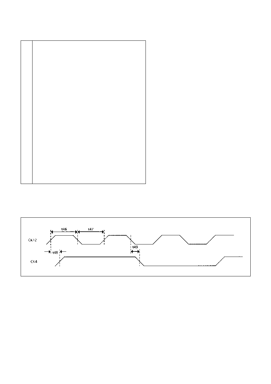
t45
Minimum RESETN pulse width
90
nS
t46
Minimum CK12 high
33
nS
t47
Minimum CK12 low
20
nS
t48
CK12
to CK4
90
nS
t49
CK12
to CK4
90
nS
t50
HALTREQN pulse width
1t
t51
HALTREQN
to HALTEDN
55
nS
t52
HALTREQN
to CODENN
1t
2t
t53
CODENN
to CODENN
2t
t54
RT-RT minimum validation time
1) RT1 = 0
RT0 = 0
55.75
56.25
uS
2) RT1 = 0
RT0 = 1
61 75
62.25
uS
3) RT1 = 1
RT0 = 0
83.75
84.25
uS
4) RT1 = 1
RT0 = 1
147.75
148.25
uS
t55
HALTREQN setup for next message wrt to INCMDN
150
nS
t56
R/WN
to R/WN
RT-BC Report cycle
80t
t57
BUFENN
to BUFENN
Data word to report word
29t
t58
BC intermessage gap
1) without a No Operation instruction
20
uS
2) with a No Operation instruction
28
uS
t59
CODENN interval high between received status
24t
and report word during report cycle
t60
CODENN interval between report word and
6t
next message fetch for continuous operation
t61
CODEN interval between BC Noop data
pointer fetch and report word
5t
t62
INCMDN
to INCADDRN
1t
t63
BUSYREQN
to BUSYACKN
60
nS
t64
BUSYREQN
to BUSYACKN
60
nS
t65
INCMDN
to BUSYACKN
60
nS
t66
INCMDN
to BUSYACKN
100
nS
t67
CK4
to R/WN/BUFENN/CO/C1/CODENN/MDTN
115
nS
Mil-Std-883, method 5005, subgroups 9, 10, 11
Notes:
1. t = CK4 period, t
12
= CK12 period
2. Times quoted as typical means a fixed number of CK4 clock cycles but excludes slight variations due to
propagation delays.
Conditions: V
dd
= 4.5 to 5.5V, T
amb
= -55
∞
C to +125
∞
C, V
IL
= 0V, V
IH
= 4V, V
OUT
Threshold = 1.5V except t
2
where measured
by a 1V change in output voltage. Load = 50pf except t
2
where additional 1K load to 0V or V
DD
.
Figure 12: AC Electrical Characteristics (continued)
MA3690/1/3
19/41
LIST OF TIMINGS
14
Clock Timing
15
Power Up Clear Initialisation
16
Subsystem Reset
17
Minimum No Response Timeout
18
Abort
19
Start of Transmission Detect
20
End of Transmission Detect
21
RT Command Reception and Subsystem Status Read
22
BC-RT Data Transfer (Non Mode) + Status
23
RT Status + RT-BC Data Transfer (Non Mode)
24
Received Mode Data Transfer + Status
25
RT Status + Transfer Mode Data Transfer
26
Broadcast BC-RT Data Transfer (Non Mode)
27
RT-Broadcast Received Mode Data Transfer
28
Mode Command No Data (TIR)
29
Remote Terminal Response Time
30
RT-RT Validation Timeout
31
Remote Terminal Busy Handshake
32
RT Status Load
33
BC-Message Fetch Sequence
34
BC-Report Cycle (shown for RT-RT no data to subsystem)
35
RT-BC Report Cycle
36
BC Intermessage Gap
37
BC-No Operation
38
BC-Self Test (Report Sequence)
39
BC-Passive Monitor
40
BC-Retry
41
BC-Data Transfer Handshake
Figure 13: List of Timings
TIMING DIAGRAMS
Figure 14: Clock Timing

MA3690/1/3
20/41
Figure 15: Power Up Clear Initialisation
Note: If the first command to the RT
following power up is to be TLSW
then initialisation should be via PUC.
PUC is driven by the subsystem.
Figure 16: Subsystem Reset
* RESET must be driven from
subsystem via an open drain/
collector device

MA3690/1/3
21/41
Figure 17: Minimum No Response Timeout
This value is programmable using the RT0/RT1 inputs
Figure 19: Start of Transmission Detect
Note: Detection is sync + 3 data bits
Figure 18: Abort
This sequence will also occur at the end of each message unless a new message is received.

MA3690/1/3
22/41
Figure 20: End of Transmission Detect
Figure 21: RT Command Reception and Subsystem Status Read
Note: Quote time pulse as typical, except t
1
, t
2
, t
3
and t
4
.

MA3690/1/3
23/41
Figure 22: BC-RT Data Transfer (Non-Mode) + Status
Figure 23: RT Status + RT-BC Data Transfer (Non Mode)
Note: For successive data words
DTRQ
to DTRQ
= 80 x CK4 periods (20
µ
s)

MA3690/1/3
24/41
Figure 24: Received Mode Data Transfer + Status
Figure 25: RT Status + Transfer Mode Data Transfer
Note: Exception MDT is not active for TLC, TBIT

MA3690/1/3
25/41
Figure 26: Broadcast BC-RT Data Transfer (Non Mode)
Figure 27: RT-Broadcast Received Mode Data Transfer
Note: MDT, MDR are not active for m/c STSD and ORSTSD

MA3690/1/3
26/41
Figure 28: Mode Command No Data (TIR)
Note: 1. SYNC m/c.
2. Self test m/c - takes 668
µ
s from end of Status transmission on 1553 Bus.
3. Reset m/c/ - Reset pulse 3 x CK4 after TXCN
this prevents
ABORT
pulse following this command and fires
EOT high and remains high.
Figure 29: Remote Terminal Response Time
Figure 30: RT-RT Validation Timeout

MA3690/1/3
27/41
Figure 31: Remote Terminal Busy Handshake
Figure 32: RT Status Load

MA3690/1/3
28/41
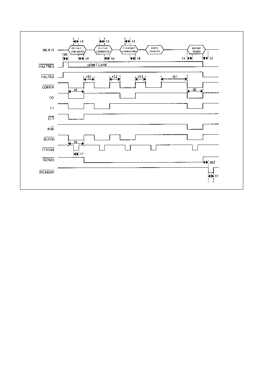
Figure 33: BC-Message Fetch Sequence
Note:
BUFEN
is not active for the DATA POINTER WORD as the 3690/1 does not use the word. It is required by
subsystem only.

MA3690/1/3
29/41
Figure 34: BC-Report Cycle (shown for RT-RT no data to subsystem)
Note: for DATA to SUBSYSTEM
GBR
(no mode) or
MDR
(mode data) will pulse as shown - otherwise
GBR
,
MDR
do not pulse

MA3690/1/3
30/41
Figure 35: RT-BC Report Cycle
Figure 36: BC Intermessage Gap
MA3690/1/3
31/41
Figure 37: BC - No Operation

MA3690/1/3
32/41
Figure 38: BC - Self Test (Report Sequence)
Figure 39: BC - Passive Monitor

MA3690/1/3
33/41
Figure 40: BC - Retry
Note: The message fetch sequence is not repeated for any retries. It is therefore essential that the subsystem zeros the
DATA word address counter for each RETRY. This is simply achieved by using CLD to clear the counter and DTAK to
increment the counter.
Figure 41: BC - Data Transfer Handshake

MA3690/1/3
34/41
OUTLINES
Figure 42a: 48-Lead Ceramic DIL (solder seal) - Package Style C
Ref.
Min.
Nom.
Max.
A
-
-
4.37 (0.172)
A
1
1.016 (0.04)
-
1.53 (0.060)
b
0.40 (0.016)
-
0.508 (0.020)
c
0.20 (0.009)
-
0.305 (0.012)
D
-
-
61.57 (2.424)
e
-
2.54 (0.100)
-
e
1
-
15.24 (0.600)
-
H
4.71 (0.185)
-
5.38 (0.212)
M
E
-
-
15.75 (0.620)
W
-
-
1.53 (0.060)
Dimensions in mm (inches)
GPS XG426

MA3690/1/3
35/41
Figure 42b: 48-Lead Ceramic DIL (solder seal) - Package Style C
Note: On the MA3693 RT1 is replaced by Terminal Flag TFN (TTL Output)
TRANSCEIVER CHIP (MA3690)
TERMINAL CONTROLLER CHIP (MA3691)
See Note -

MA3690/1/3
36/41
Figure 42c: 48-Lead Ceramic DIL (solder seal) - Package Style C
TRANSCEIVER CHIP (MA3693)
(For applications that require access to Terminal Flag)
See Note -
Note: The MA3693 has Terminal Flag (TFN) latched signal OUTPUT on pin 13 (TTL).
This replaces the RT1 signal INPUT that is used on the MA3690 standard version.

MA3690/1/3
37/41
Figure 43a: 64-Lead Topbraze Flatpack (Package Style F)
Ref.
Min.
Nom.
Max.
A
-
-
2.1 (0.083)
A
1
0.96 (0.038)
-
1.07 (0.042)
b
0.41 (0.016)
-
0.51 (0.020)
c
0.178 (0.007)
-
0.254 (0.010)
D1,D2
-
-
23.11 (0.910)
E
15.54 (0.612)
-
15.95 (0.628)
e
-
1.27 (0.050)
-
L
8.89 (0.350)
-
9.27 (0.365)
Z
1.73 (0.068)
-
2.16 (0.085)
Dimensions in mm (inches)
GPS XG487

MA3690/1/3
38/41
Figure 43b: 64-Lead Topbraze Flatpack (Package Style F)

MA3690/1/3
39/41
Figure 43c: 64-Lead Topbraze Flatpack (Package Style F)

MA3690/1/3
40/41
RADIATION TOLERANCE
Total Dose Radiation Testing
For product procured to guaranteed total dose radiation
levels, each wafer lot will be approved when all sample
devices from each lot pass the total dose radiation test.
The sample devices will be subjected to the total dose
radiation level (Cobalt-60 Source), defined by the ordering
code, and must continue to meet the electrical parameters
specified in the data sheet. Electrical tests, pre and post
irradiation, will be read and recorded.
GEC Plessey Semiconductors can provide radiation
testing compliant with Mil-Std-883 test method 1019, Ionizing
Radiation (Total Dose).
Total Dose (Function to specification)*
3x10
5
Rad(Si)
Transient Upset (Stored data loss)
5x10
10
Rad(Si)/sec
Transient Upset (Survivability)
>1x10
12
Rad(Si)/sec
Neutron Hardness (Function to specification)
>1x10
15
n/cm
2
Single Event Upset**
<1x10
-10
Errors/bit day
Latch Up
Not possible
* Other total dose radiation levels available on request
** Worst case galactic cosmic ray upset - interplanetary/high altitude orbit
Figure 44: Radiation Hardness Parameters
ORDERING INFORMATION
Unique Circuit Designator
S
R
Q
H
Radiation Hard Processing
100 kRads (Si) Guaranteed
300 kRads (Si) Guaranteed
1000 kRads (Si) Guaranteed
Radiation Tolerance
C
F
N
Ceramic DIL (Solder Seal)
Flatpack (Solder Seal)
Naked Die
Package Type
QA/QCI Process
(See Section 9 Part 4)
Test Process
(See Section 9 Part 3)
Assembly Process
(See Section 9 Part 2)
L
C
D
E
B
S
Rel 0
Rel 1
Rel 2
Rel 3/4/5/STACK
Class B
Class S
Reliability Level
MAx3690xxxxx
MAx3691xxxxx
MAx3693Cxxxx
For details of reliability, QA/QC, test and assembly
options, see `Manufacturing Capability and Quality
Assurance Standards' Section 9.

MA3690/1/3
41/41
CUSTOMER SERVICE CENTRES
France, Benelux, Italy and Spain Tel: +33 (0)1 69 18 90 00. Fax: +33 (0)1 64 46 54 50
North America Tel: 011-800-5554-5554. Fax: 011-800-5444-5444
UK, Germany, Scandinavia & Rest Of World Tel: +44 (0)1522 500500. Fax: +44 (0)1522 500020
SALES OFFICES
France, Benelux, Italy and Spain Tel: +33 (0)1 69 18 90 00. Fax: +33 (0)1 64 46 54 50
Germany Tel: 07351 827723
North America Tel: (613) 723-7035. Fax: (613) 723-1518. Toll Free: 1.888.33.DYNEX (39639) /
Tel: (831) 440-1988. Fax: (831) 440-1989 / Tel: (949) 733-3005. Fax: (949) 733-2986.
UK, Germany, Scandinavia & Rest Of World Tel: +44 (0)1522 500500. Fax: +44 (0)1522 500020
These offices are supported by Representatives and Distributors in many countries world-wide.
© Dynex Semiconductor 2000 Publication No. DS3587-5 Issue No. 5.0 January 2000
TECHNICAL DOCUMENTATION ≠ NOT FOR RESALE. PRINTED IN UNITED KINGDOM
HEADQUARTERS OPERATIONS
DYNEX SEMICONDUCTOR LTD
Doddington Road, Lincoln.
Lincolnshire. LN6 3LF. United Kingdom.
Tel: 00-44-(0)1522-500500
Fax: 00-44-(0)1522-500550
DYNEX POWER INC.
Unit 7 - 58 Antares Drive,
Nepean, Ontario, Canada K2E 7W6.
Tel: 613.723.7035
Fax: 613.723.1518
Toll Free: 1.888.33.DYNEX (39639)
This publication is issued to provide information only which (unless agreed by the Company in writing) may not be used, applied or reproduced for any purpose nor form part of any order or contract nor to be regarded
as a representation relating to the products or services concerned. No warranty or guarantee express or implied is made regarding the capability, performance or suitability of any product or service. The Company
reserves the right to alter without prior notice the specification, design or price of any product or service. Information concerning possible methods of use is provided as a guide only and does not constitute any
guarantee that such methods of use will be satisfactory in a specific piece of equipment. It is the user's responsibility to fully determine the performance and suitability of any equipment using such information and
to ensure that any publication or data used is up to date and has not been superseded. These products are not suitable for use in any medical products whose failure to perform may result in significant injury
or death to the user. All products and materials are sold and services provided subject to the Company's conditions of sale, which are available on request.
All brand names and product names used in this publication are trademarks, registered trademarks or trade names of their respective owners.
http://www.dynexsemi.com
e-mail: power_solutions@dynexsemi.com
Datasheet Annotations:
Dynex Semiconductor annotate datasheets in the top right hard corner of the front page, to indicate product status. The annotations are as follows:-
Target Information: This is the most tentative form of information and represents a very preliminary specification. No actual design work on the product has been started.
Preliminary Information: The product is in design and development. The datasheet represents the product as it is understood but details may change.
Advance Information: The product design is complete and final characterisation for volume production is well in hand.
No Annotation: The product parameters are fixed and the product is available to datasheet specification.