 | –≠–ª–µ–∫—Ç—Ä–æ–Ω–Ω—ã–π –∫–æ–º–ø–æ–Ω–µ–Ω—Ç: SHM-14 | –°–∫–∞—á–∞—Ç—å:  PDF PDF  ZIP ZIP |
IN N O VA T IO N a n d E X C E L L E N C E
Æ
Æ
SHM-14
Ultra-Fast, 14-Bit Linear
Monolithic Sample-Hold Amplifiers
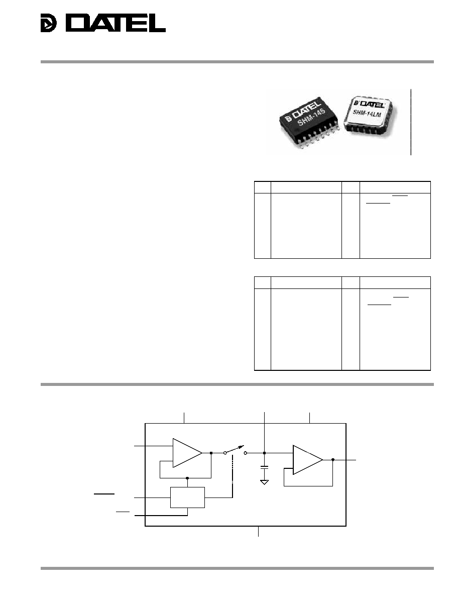
Figure 1. SHM-14 Functional Block Diagram
1, 5, 8
ANALOG
OUTPUT
3
15
ANALOG INPUT
9
SAMPLE/HOLD
SWITCH
DRIVE
16
13
10, 11, 14
12
GROUND
EXTERNAL HOLD
CAPACITOR
≠5V SUPPLY
+5V SUPPLY
+1
+1
SAMPLE/HOLD
C
H
15pF
2, 4, 6, 7
DO NOT CONNECT
Note: SOIC Package Pinouts Shown
FEATURES
∑
Fast acquisition time:
10ns to ±0.1%
20ns to ±0.024%
25ns to ±0.012%
∑
±0.0012% Nonlinearity
∑
65µV rms output noise
∑
250MHz small signal bandwidth
∑
70MHz full power bandwidth
∑
≠80dB feedthrough
∑
1ps Aperture jitter
∑
250mW power dissipation
∑
Low cost
GENERAL DESCRIPTION
The SHM-14 is an extremely high-speed and accurate
monolithic sample-and-hold amplifier designed for fast data
acquisition applications. The SHM-14 is accurate (±0.5 LSB to
14-bits over the full military temperature range) and is very fast
(10ns and 20ns acquisition times to accuracies of 10 and 12
bits respectively). With this high performance and a full power
bandwidth of 70MHz, the SHM-14 is an ideal device for driving
flash and high-resolution subranging A/D converters.
A careful design optimizes the device for accuracy and speed
over the full military temperature range. The droop rate is a low
±2mV/µs and can be further reduced by adding an optional
external hold capacitor. The 30mA output current and
guaranteed specifications for a 100
load provide high drive
capability. Operating from ± 5V supplies, the SHM-14
consumes only 250mW of power.
The SHM-14 is built using a fast complementary bipolar
process. The device is available in both military and industrial
temperature ranges. The SHM-14 is packaged in a 16-pin
plastic SOIC or in a 20-pin ceramic LCC.
1
NOT CONNECTED
2
≠5V SUPPLY
3
NOT CONNECTED
4
ANALOG INPUT
5
NOT CONNECTED
6
DO NOT CONNECT
7
≠5V SUPPLY
8
DO NOT CONNECT
9
DO NOT CONNECT
10
≠5V SUPPLY
20
NOT CONNECTED
19
SAMPLE/HOLD
18
SAMPLE/HOLD
17
+5V SUPPLY
16
NOT CONNECTED
15
EXT. CAPACITOR
14
GROUND
13
+5V SUPPLY
12
+5V SUPPLY
11
ANALOG OUTPUT
PIN
FUNCTION
PIN
FUNCTION
INPUT/OUTPUT CONNECTIONS -- CLCC
16
SAMPLE/HOLD
15
SAMPLE/HOLD
14
+5V SUPPLY
13
EXT. CAPACITOR
12
GROUND
11
+5V SUPPLY
10
+5V SUPPLY
9
ANALOG OUTPUT
1
≠5V SUPPLY
2
DO NOT CONNECT
3
ANALOG INPUT
4
DO NOT CONNECT
5
≠5V SUPPLY
6
DO NOT CONNECT
7
DO NOT CONNECT
8
≠5V SUPPLY
PIN
FUNCTION
PIN
FUNCTION
INPUT/OUTPUT CONNECTIONS -- SOIC
DATEL, Inc., 11 Cabot Boulevard, Mansfield, MA 02048-1151 (U.S.A.)
∑
Tel: (508) 339-3000 Fax: (508) 339-6356
∑
For immediate assistance (800) 233-2765
SHM-14
Æ
Æ
INPUTS
MIN.
TYP.
MAX.
UNITS
Input Voltage Range
≠2.5
--
+2.5
Volts
Input Impedance
0.3
1
--
M
Digitals Inputs (Balanced ECL)
Logic Levels
Logic 1
≠1.5
--
+1.8
Volts
Logic 0
≠2.5
--
+0.8
Volts
Logic Loading
Logic 1
--
+10
+50
µA
Logic 0
--
≠30
≠150
µA
Output Voltage Range
≠2.5
--
+2.5
Volts
Output Current
∑
± 30
--
--
mA
Output Impedance (dc)
--
0.3
1
Stable Capacitive Load
--
--
50
pF
Nonlinearity (±1V)
+25∞C
--
±0.0012
--
%
≠40 to +85∞C
--
--
±0.002
%
≠55 to +125∞C
--
--
±0.003
%
Sample Mode Offset
+25∞C
--
±12
--
mV
≠40 to +85∞C
--
--
±20
mV
≠55 to +125∞C
--
--
±30
mV
Pedestal
+25∞C
--
±3
--
mV
≠40 to +85∞C
--
--
±20
mV
≠55 to +125∞C
--
--
±20
mV
Gain, +25∞C
+0.98
+0.995
--
V/V
Gain Drift (±1V)
≠40 to +85∞C
--
--
±20
ppm/∞C
≠55 to +125∞C
--
--
±30
ppm/∞C
Aperture Delay
≠40 to +85∞C
--
2
--
ns
≠55 to +125∞C
--
2
--
ns
Aperture Jitter
≠40 to +85∞C
--
1
--
ps rms
≠55 to +125∞C
--
1
--
ps rms
Harmonic Distortion (±1V)
dc to 1MHz
--
≠72
--
dB
dc to 10MHz
+25∞C
--
≠58
--
dB
≠40 to +85∞C
--
--
≠50
dB
≠55 to +125∞C
--
--
≠48
dB
Acquisition Time (±0.012%, ±2V)
≠40 to +85∞C
--
25
--
ns
≠55 to +125∞C
--
35
--
ns
Acquisition Time (±0.024%, ±2V)
≠40 to +85∞C
--
20
35
ns
≠55 to +125∞C
--
25
40
ns
Acquisition Time (±0.05%, ±2V)
≠40 to +85∞C
--
19
30
ns
≠55 to +125∞C
--
20
35
ns
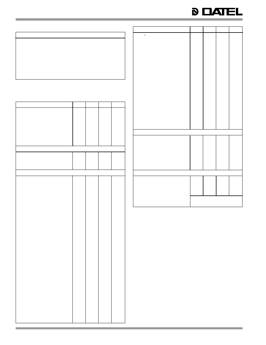
ABSOLUTE MAXIMUM RATINGS
PARAMETERS
LIMITS
UNITS
+5V Supply
0 to +6
Volts
≠5V Supply
0 to ≠6
Volts
Analog Input
+5V Supply ≠1
Volts
≠5V Supply +1
Volts
Continuous Output Current
±50
mA
Digital Inputs
<Supply Voltages
Volts
Junction Temperature
+175
∞C
Lead Temperature (10 seconds)
+300
∞C
Output shorted to any supply will cause permanent damage.
OUTPUTS
PERFORMANCE
FUNCTIONAL SPECIFICATIONS
(Apply over the operating temperature range using a 100
resistive load, 10pF
capacitive load, ECL digital input levels, and ±5V nominal supplies, unless specified.)
TECHNICAL NOTES
The SHM-14 employs an open loop architecture in order to
achieve its superior high-speed characteristics. The first stage
buffer amplifier, which charges the hold capacitor, incorporates the
sample-and-hold switch into its design. This technique allows for a
fast acquisition time which is not limited by slew current like the
traditional Schottky diode bridge switch. The output amplifier uses
a closed loop voltage feedback design which provides a low (0.3
,
typical) output impedance. Gain and linearity are not affected by
heavy loads.
The design has been optimized to achieve the high accuracy associ-
ated with fast transient responses over the full military temperature
range. During the track-to-hold transient, the integral nonlinearity is
not affected and the pedestal remains constant over the full ±2.5V
input range.
An external hold capacitor can be added to the 15pF internal hold
capacitor to obtain a lower droop rate (the droop rate is propor-
tional to the inverse of the total hold capacitor value) without
increasing transient response times by more than few ns. Settling
and acquisition times are typically increased by 5ns and 10ns
respectively for 47pF and 100pF external hold capacitors. The
external hold capacitor should not exceed 100pF.
Acquisition Time (±0.1%, ±2V)
≠40 to +85∞C
--
10
16
ns
≠55 to +125∞C
--
10
19
ns
Hold Mode Settling (±0.012%)
≠40 to +85∞C
--
12
--
ns
≠55 to +125∞C
--
15
--
ns
Hold Mode Settling (±0.024%)
≠40 to +85∞C
--
7
18
ns
≠55 to +125∞C
--
7
18
ns
Hold Mode Settling (±0.05%)
≠40 to +85∞C
--
6
16
ns
≠55 to +125∞C
--
6
16
ns
Hold Mode Settling (±0.1%)
≠40 to +85∞C
--
5
12
ns
≠55 to +125∞C
--
5
12
ns
Slew Rate
±300
±430
--
V/µs
Full Power Bandwidth (±1V)
45
70
--
MHz
Small Signal Bandwidth
100
250
--
MHz
Output Noise, Hold Mode
--
65
--
µVrms
Feedthrough (2V Step)
--
≠80
--
dB
Droop Rate
+25∞C
--
±2
±6
mV/µs
≠40 to +85∞C
--
±5
±15
mV/µs
≠55 to +125∞C
--
±10
±30
mV/µs
Power Supply Range
+5V Supply
+4.5
+5
+5.5
Volts
≠5V Supply
≠5.5
≠5
≠4.5
Volts
Power Supply Current
+5V Supply
+17
+25
+30
mA
≠5V Supply
≠17
≠25
≠30
mA
Power Dissipation
170
250
300
mW
Power Supply Rejection Ratio
40
60
--
dB
Operating Temp. Range, Case
SHM-14S, SHM-14L
≠40
--
+85
∞C
SHM-14LM
≠55
--
+125
∞C
Storage Temperature Range
≠65
--
+150
∞C
Package Type
SHM-14S
16-Pin plastic SOIC
SHM-14L, SHM-14LM
20-Pin ceramic LCC
Footnotes:
∑
Short circuit protection at ±50mA.
ENVIRONMENTAL
POWER SUPPLY REQUIREMENTS
PERFORMANCE (Cont.)
MIN.
TYP.
MAX. UNITS
2
SHM-14
Æ
Æ
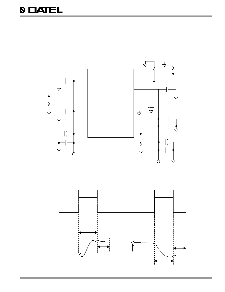
HOLD
SAMPLE
-0.8 V
-1.8 V
-0.8 V
-1.8 V
+1 V
-1 V
+1 V
-1 V
Acquisition
Time to
±0.024%
Track-to-hold Settling
to ±0.024%
20ns typ.
7ns typ.
20ns typ.
7ns typ.
Feedthrough -80dB
SAMPLE
HOLD
ANALOG
INPUT
ANALOG
OUTPUT
HOLD
SAMPLE
GROUNDING AND LAYOUT
Obtaining fully specified performance from the SHM-14 requires
careful attention to pc-board layout and power supply decoupling.
For optimal performance, tie all grounds directly to a large ana-
log ground plane beneath and around the package. Bypass all
power supplies to ground with 10µF tantalum capacitors in par-
allel with 0.1µF ceramic capacitors.
Locate the bypass capacitors as close to the unit as possible.
For best performance, controlled impedance transmission line
techniques, such as microstrip, should be used. Mount all com-
ponents as close to the required pins as possible. It is strongly
recommended that the SHM-14 not be socket-mounted.
Figure 2. SHM-14 Simplified Connection Diagram
Figure 3. SHM-14 Control and Timing
≠5V SUPPLY
≠ 5V SUPPLY
≠ 5V SUPPLY
INPUT
SAMPLE / HOLD
EXTERNAL HOLD
CAPACITOR
GROUND
+5V SUPPLY
ANALOG OUTPUT
+5V SUPPLY
ANALOG
INPUT
ANALOG
OUTPUT
HOLD
SAMPLE
SHM-14
50
+
0.1µF
10µF
0.1µF
0.1µF
≠ 5V
0.1µF
0.1µF
+5V
0.1µF
10µF
0.1µF
SAMPLE / HOLD
+5V SUPPLY
50
50
R Load
100
1 (2)
3 (4)
5 (7)
8 (10)
16 (19)
15 (18)
14 (17)
13 (15)
12 (14)
11 (13)
10 (12)
9 (11)
NOTES:
1. Pin numbers in ( ) are for CLCC package.
2. For SOIC package:
Pins 2, 4, 6, 7 DO NOT CONNECT
3. For CLCC package:
Pins 1, 3, 5, 16, 20 NOT CONNECTED
Pins 6, 8, 9 DO NOT CONNECT
Refer to Table 1 for optional
HOLD capacitor values.
C
HOLD
+
3

SHM-14
Æ
Æ
Figure 4. SHM-14 Evaluation Board Schematic
Operating
Type of HOLD Capacitor
Model
Temperature Range
(Ceramic,
100pF, ±10%)
SHM-14L, -14S
≠40 to +85∞C
Type I or II, NPO or X7R
SHM-14LM
≠55 to +125∞C
Type I or NPO
Table 1. Optional External HOLD Capacitor
≠5V SUPPLY
≠5V SUPPLY
≠5V SUPPLY
INPUT
SAMPLE / HOLD
+5V SUPPLY
EXTERNAL HOLD
CAPACITOR
GROUND
+5V SUPPLY
OUTPUT
+5V SUPPLY
ANALOG
INPUT
+5V SUPPLY
ANALOG
OUTPUT
HOLD
SAMPLE
≠5V SUPPLY
≠5V SUPPLY
SHM-14
SAMPLE / HOLD
0.1µF
0.1µF
0.1µF
0.1µF
0.1µF
0.1µF
51
130
82
130
82
2
7
10
4
19
18
17, 20
15
14, 16
12
13
11
13
14
5
6, 7, 8, 9, 10
20
16, 17, 18, 19
11, 12, 15
GROUND
1, 2, 3, 4
GROUND PLANE
Evaluation Board
for CLCC-20 Version
Refer to Table 1. for optional
HOLD capacitor values.
C
HOLD
4
SHM-14
Æ
Æ
1
2
3
4
6
7
8
9
10
11
12
13
20
15
16
14
19
18
17
5
0.95
(24.13)
1.10
(27.94)
0.85
(21.59)
0.100
(2.54)
INCHES
(mm)
0.43
(11)
0.13
(3.3)
0.018
(0.45)
(TOP VIEW)
1
2
3
4
6
7
8
9
10
11
12
13
20
15
16
14
19
18
17
5
C
E
X
T
R1
R3
R4
R5
R6
C1
C2
C3
C4
C5
C6
C7
(BOTTOM VIEW)
PLASTIC
STANDOFF
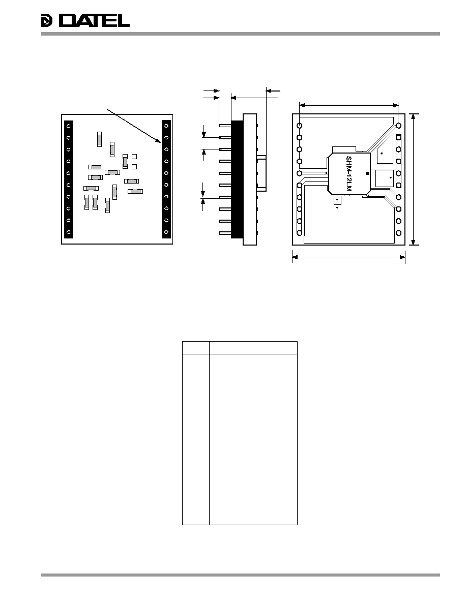
Figure 5. SHM-14 Evaluation Board Dimensions
SHM-14 Evaluation Board Connections
1
GROUND
2
GROUND
3
GROUND
4
GROUND
5
ANALOG OUTPUT
6
+5V SUPPLY
7
+5V SUPPLY
8
+5V SUPPLY
9
+5V SUPPLY
10
+5V SUPPLY
11
≠5V SUPPLY
12
≠5V SUPPLY
13
HOLD
14
SAMPLE
15
≠5V SUPPLY
16
≠5V SUPPLY
17
≠5V SUPPLY
18
≠5V SUPPLY
19
≠5V SUPPLY
20
ANALOG INPUT
PIN
FUNCTION
5