 | –≠–ª–µ–∫—Ç—Ä–æ–Ω–Ω—ã–π –∫–æ–º–ø–æ–Ω–µ–Ω—Ç: M-985-01 | –°–∫–∞—á–∞—Ç—å:  PDF PDF  ZIP ZIP |

Part #
Description
M-985-01P
22-pin plastic DIP
M-985-01S
20-pin plastic SOIC
M-985-01T
20-pin plastic SOIC,Tape and Reel
www.clare.com
DS-M985-01-R1
M-985-01
Precise Call Progress and
Special Information Tone Generator
1
Features
∑
Precise detection of call progress tones
∑
Linear (analog) input
∑
Digital (CMOS compatible), tri-state outputs
∑
22-pin DIP and 20-pin SOIC
∑
Single supply 3 to 5 volt (low power CMOS)
∑
Inexpensive 3.58 MHz crystal time base
∑
Wide dynamic range (30 dB)
∑
Lower power consumption (power-down mode)
∑
425 Hz detection
∑
Special Information Tone (SIT) Detection
Applications
∑
Automatic dialers
∑
Dialing modems
∑
Traffic measurement equipment
∑
Test equipment
∑
Service evaluation
∑
Billing systems
Description
The M-985-01 is an integrated circuit precise tone
detector for call progress and special information
tones (SIT), as defined by CCITT.
The use of integrated circuit techniques allows the
M-985-01 to pack the eight filters for call progress
detection into a single 22-pin DIP or a 20-pin SOIC. A
3.58 MHz crystal-controlled time base guarantees
accuracy and repeatability.
The M-985-01 combines the call progress detection of
the M-982-02 and the SIT detection of the M-984-02.
It has an operating voltage range down to 3V. It has
low power consumption under normal operating con-
ditions. A power down (PD) feature is provided to fur-
ther reduce power consumption when inactive.
Block Diagram
Pin Diagram
Ordering Information

Specifications
Parameter
Conditions
Min
Max
Units
Notes
Operating V
DD
-
2.7
5.5
V
-
Conditions
Power supply noise
0.1 - 5 kHz
-
20
mV p-p
-
Power
Current drain (I
DD
)
-
-
15
mA
-
V
REF
V
REF
-
48% of V
DD
52% of V
DD
V
-
Impedance
-
3.25
8.25
k
Signal
Frequency range
in-band signal
-1
+1
% of f
o
1
Detection,
Level: V
DD
= 5.0v
XRANGE = open
-30 (24.5 mV)
0 (775 mV)
dBm
all tones except
XRANGE = V
SS
-40 (7.8 mV)
-10 (245 mV)
dBm
SIT tones.
Level: V
DD
= 3.0V
XRANGE = open
-33 (17.4 mV)
-3 (549 mV)
dBm
XRANGE = V
SS
-43 (5.5 mV)
-13 (173.5 mV)
dBm
Duration (t
DD
)
-
200
-
ms
Signal drop out bridging time (t
BB
)
-
-
20
ms
Level skew between adjacent
for detection of both
-
6
dB
inband signals
High level to low level signal for
High = 0 dBm (775 mV)
1
-
s
detection of both (t
IL
)
Low = -30 dBm (24.5 mV)
Time to output (t
DO
)
SIGIN
-24 dBm
-
200
ms
SIGIN < -24 dBm
-
240
ms
Time from OUT n to STROBE (t
DS
)
-
-
10
µs
Signal Detection, Frequency Range
-
-
-
-
2
940, 1400, 1800 Level: V
DD
= 5.0V
XRANGE = open
-30 (24.5 mV)
0 (775 mV)
dBm
-
Hz
XRANGE = V
SS
-40 (7.8 mV)
-10 (245 mv)
dBm
Level: V
DD
= 3.0V
XRANGE = open
-33 (17.4 mV)
-3 (549 mV)
dBm
XRANGE = V
SS
-43 (5.5 mV)
-13 (173.5 mV)
dBm
Duration
-
50
-
ms
Signal drop out bridging time (t
BB
)
-
-
15
ms
Signal to noise ratio
-
16
-
dB
Signal Rejection, Frequency range
-
-6
+6
% of f
0
1
all tones except Level: V
DD
= 5.0V
XRANGE = open
-
-50 (2.5 mV)
dBm
-
SIT tones.
XRANGE = V
SS
-
-60 (0.8 mv)
dBm
Level: V
DD
= 3.0V
XRANGE = open
-
-53 (1.7 mV)
dBm
XRANGE = V
SS
-
-65 (.55 mV)
dBm
Interval duration (t
ID
)
-
160
-
ms
Time to end of output (t
IO
)
-
-
200
ms
www.clare.com
2
M-985-01
Rev. 1
Absolute Maximum Ratings
Storage Temperature
-40 to 150∞C
Operating Ambient Temperature
-40 to 85∞C
V
DD
7V
Input Voltage on SIGIN
V
SS
- 6.5 to V
DD
+ 0.3V
Input Voltages (except SIGIN)
V
SS
- 0.3 to V
DD
+ 0.3 V
Lead Soldering Temperature
260∞ C for 5 seconds
Note:
Exceeding these ratings may permanently damage the M-985-01.
Absolute Maximum Ratings are stress ratings. Stresses in
excess of these ratings can cause permanent damage to
the device. Functional operation of the device at these or
any other conditions beyond those indicated in the opera-
tional sections of this data sheet is not implied. Exposure of
the device to the absolute maximum ratings for an extend-
ed period may degrade the device and effect its reliability.

Specifications (Continued)
Parameter
Conditions
Min
Max
Units
Notes
Signal Rejection, Frequency Range
-
-
-
-
2
950, 1400, 1800 Level: V
DD
= 5.0V
XRANGE = open
-
-40 (7.8 mV)
dBm
-
Hz
XRANGE = V
SS
-
-50 (2.5 mV)
dBm
-
Level: V
DD
= 3.0V
XRANGE= open
-
-43 (5.5 mV)
dBm
-
XRANGE= V
SS
-
-53 (1.7 mV)
dBm
-
Duration
-
50
ms
-
-
Outputs
OUT n,
V
OL
I
SINK
= -1mA
-
0.5
V
-
STROBE pins
V
OH
I
SOURCE
= 1mA
V
DD
-0.5
-
V
-
OUT n pins
I
OZ
V
O
=V
DD
, V
SS
-
1
µA
-
Inputs
EN, OE,
V
IL
-
-
0.5
V
-
XRANGE, MODE, V
IH
V
DD
= 5V
V
DD
- 2.0
-
V
-
PD pins
V
DD
= 2.7V
V
DD
- 0.5
-
V
-
Pull-up and
MODE = V
SS
V
DD
= 5V
12.5
50
µA
-
Pull-down currents
V
DD
= 2.7V
4
20
µA
-
/XRANGE = V
SS
-
2
6
µA
-
MODE2 = V
DD
V
DD
= 5V
12.5
100
µA
-
V
DD
= 2.7V
12.5
25
µA
-
PD = V
DD
-
4
10
µA
-
PD pin
Pull-down current
PD = V
DD
12.5
50
µA
-
SIGIN pin
Voltage range
-
-6.5
V
DD
V
-
Input impedance
f=500 Hz
80
-
k
-
Input spectrum
-
-
28
kHz
-
Clock
External clock
V
IL
XOUT open
-
0.2
V
-
connected to XIN V
IH
XOUT open
V
DD
-0.2
-
V
-
pin
Duty cycle
XOUT open
40
60
%
-
XIN, XOUT with
Capacitance
-
-
10
pF
-
crystal osc. active Internal resistance
-
20
-
M
-
Power up (t
PU
)
PD hi to lo
-
30
ms
-
X358 pin
V
OL
C
L
= 20 pF,
-
0.2
V
-
I
SINK
= -1mA
V
OH
C
L
= 20 pF,
V
DD
- 0.2
-
V
-
I
SOURCE
= 1mA
Duty cycle
C
L
= 20 pF
40
60
%
-
Tri-state t
EN
(High Z to Low Z)
C
L
= 50 pF,
-
250
ns
-
Operation
t
DE
(Low Z to High Z)
R
L
= 100 k
-
250
ns
Unless otherwise noted, V
DD
- V
SS
= 5V, Ta = 25∞C, PD at logical low state, and XRANGE at a logical high state. Power levels are in dBm referenced to 600 ohm. DC voltages are referenced to V
SS
.
Notes:
1. Per tone.
2. See Table 4 for detection/rejection frequencies.
M-985-01
www.clare.com
3
Rev. 1
Call Progress Tone Detection
Call progress tones are audible tones sent from switch-
ing systems to calling parties to show the status of calls.
Calling parties can identify the success of a call placed
by what is heard after dialing. The type of tone used and
its timing vary from system to system, and though
intended for human ears these signals can provide
valuable information for automated calling systems.
The M-985-01 contains five signal detectors sensitive to
the frequencies often used for these progress tones.
Electronic equipment monitoring the OUTn outputs of
the M-985-01 can determine the nature of signals pres-
ent by measuring their duty cycle. See Mechanical
Dimensions for a diagram of a circuit that could be used
to permit a microcomputer to directly monitor tones on
the telephone line. Much of the character of the
progress tones is in their duty cycle or cadence (some-
times referred to as interruption rate). This information,
coupled with level and frequency indication from the M-
985-01, can be used to decide what progress tones
have been encountered.

Truth Table
Signal Present (fo)
Mode
OUT 1
OUT 2
OUT 3
OUT 4
D425
Strobe
PD
OE
EN
350 Hz
X
1
0
0
0
X
1
0
1
1
400 Hz (Note 1)
0
0
1
0
0
X
1
0
1
1
425 Hz
X
X
X
X
X
1
1
0
1
1
440 Hz
X
1
1
0
0
X
1
0
1
1
480 Hz
X
0
0
1
0
X
1
0
1
1
620 Hz (Note 2)
1
1
0
1
0
X
1
0
1
1
950 Hz
X
0
1
1
0
X
1
0
1
1
1400 Hz
X
1
1
1
0
X
1
0
1
1
1800 Hz
X
0
0
0
1
X
1
0
1
1
350 & 440 Hz
X
1
0
0
1
X
1
0
1
1
350 & 480 Hz
X
0
1
0
1
X
1
0
1
1
350 & 620 Hz (Note 2)
1/open
1
1
0
1
X
1
0
1
1
440 & 480 Hz
X
0
0
1
1
X
1
0
1
1
440 & 620 Hz (Note 2)
X
1
0
1
1
X
1
0
1
1
480 & 620 Hz (Note 2)
X
0
1
1
1
X
1
0
1
1
Invalid Tone Combination
X
1
1
1
1
X
1
0
1
1
Other (no detect)
X
0
0
0
0
0
0
0
1
1
Any
X
0
0
0
0
0
0
1
1
X
Pin Functions
Pin
Function
OUT 1
Active high tri-state output, per Truth Table.
OUT 2
Active high tri-state output, per Truth Table.
OUT 3
Active high tri-state output, per Truth Table
OUT 4
Active high tri-state output, per Truth Table
D425
Active high tri-state output, indicates 425 Hz detection.
EN
Active high enabled, when low drives STROBE low.
OE
Active high input. When low tri-states OUT n pins.
SIGIN
Analog signal input (internally capacitive coupled).
STROBE Active high output, indicates valid OUT n or D425
VDD
Most positive power supply input pin.
VREF
Internally generated mid-power supply voltage (output)
V
SS
Most negative power supply input pin.
X358
Buffered oscillator output (3.58 MHz).
XIN
Crystal oscillator or digital clock input.
XOUT
Crystal oscillator output. Used only with a crystal. Use
X358 when clock output signal is required.
XRANGE Active low input. Adds 10 dB of gain to input stage.
MODE
Selects 400/620 Hz detector frequency, 400 Hz when
connected to V
SS
, 620 Hz when open.
PD
Power down operation, logic high inhibits internal
clock. Internal pulldown resistor.
MODE2
Tie high (V
DD
) for normal operation. Tie low or leave
open to emulate M-982 operation.
www.clare.com
4
M-985-01
Rev. 1
For example, dial tones shown in absolute Maximum
Ratings Table on page 3, are usually "on" continuously
and last until the first dial digit is received by the switch-
ing system. Line Busy, on the other hand, is turned off
and on at a rate of 1 Hz with a 50% duty cycle, or an
interruption rate of 60 times per minute (60 IPM). The
tones can be distinguished in this way. It should be
noted that while such techniques will usually be effec-
tive, there are some circumstances in which the M-985-
01 cannot be accurately used. Examples include
situations where ringback tone may be short or not
even encountered. Ringback may be provided at ring-
ing voltage frequency (20 or 30 Hz) with some harmon-
ics and may not fall in the detect range, and speech or
other strong noise may obscure tones making cadence
measurement difficult.
Standards exist and should be consulted for your par-
ticular application. In North America AT&Ts "Notes on
the Network" or EIA's RS-464 PBX standard should be
reviewed.
In Europe tone plans may vary with locale, in which
case the CEPT administration in each country must
be consulted. Outside these areas, national PTT
organizations can provide information on the systems
within their borders.
Detector Frequency Windows for SIT Tones
Detector
Low Reject
Low Accept
High Accept
High Reject
D950
835
885
1016
1070
D1400
1275
1328
1472
1527
D1800
1656
1722
1854
1924
Truth Table (Continued)
Signal Present (fo)
Mode
OUT 1
OUT 2
OUT 3
OUT 4
D425
Strobe
PD
OE
EN
Any
X
0
0
0
0
0
0
0
1
0
Any
X
High Impedance
X
0
0
1
Any
X
High Impedance
0
0
0
0
Any
X
High Impedance
X
1
0
X
Notes:
1. This output indicates 400 Hz detect when MODE is connected to V
SS
.
2. This output indicates 620 Hz detect when MODE is open or connected to V
DD
.
M-985-01
www.clare.com
5
Rev. 1
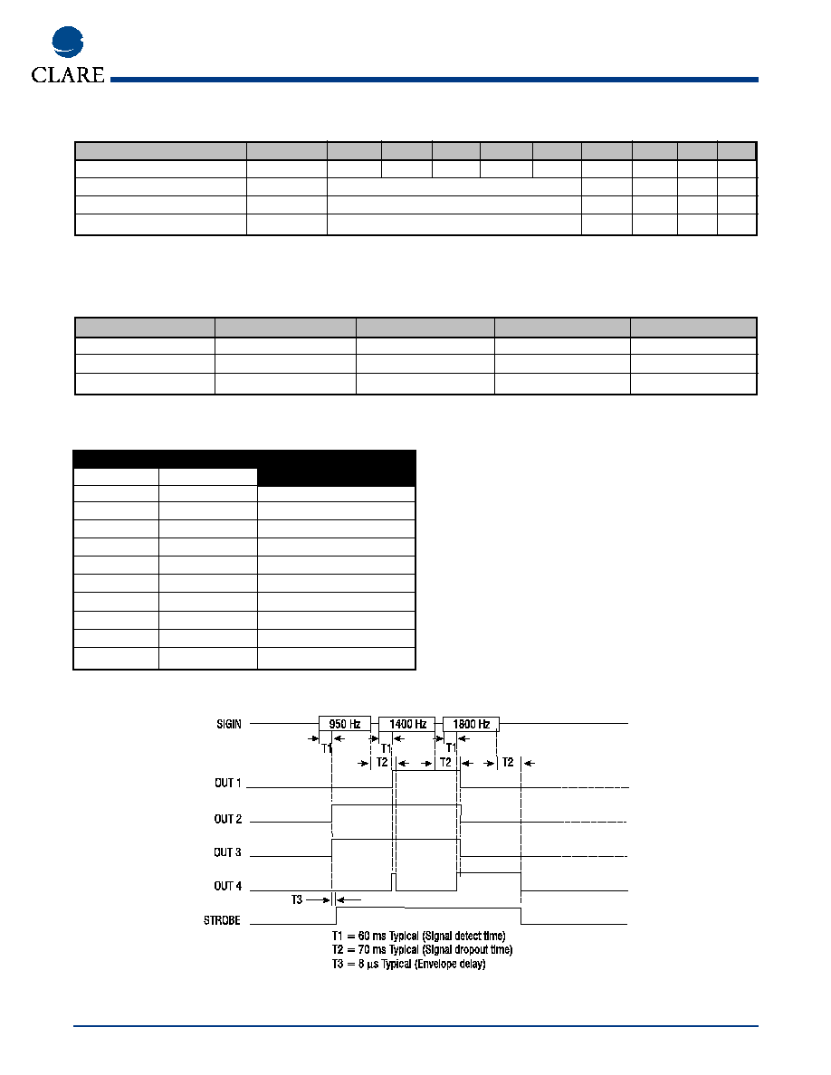
SIT Timing
Call Progress Tones
Frequency (HZ)
1
2
Use
350
440
Dial Tone
400
Off
Special
440
Off
Alert Tone
440
480
Audible Ring
440
620
Pre-empt
480
Off
Bell High Tone
480
620
Reorder (Bell Low)
350
Off
Special
620
Off
Special
425
Off
European