 | ÐлекÑÑоннÑй компоненÑ: ISO518 | СкаÑаÑÑ:  PDF PDF  ZIP ZIP |
Äîêóìåíòàöèÿ è îïèñàíèÿ www.docs.chipfind.ru
1
®
ISO518
Bidirectional
ISOLATED DIGITAL COUPLERS
DESCRIPTION
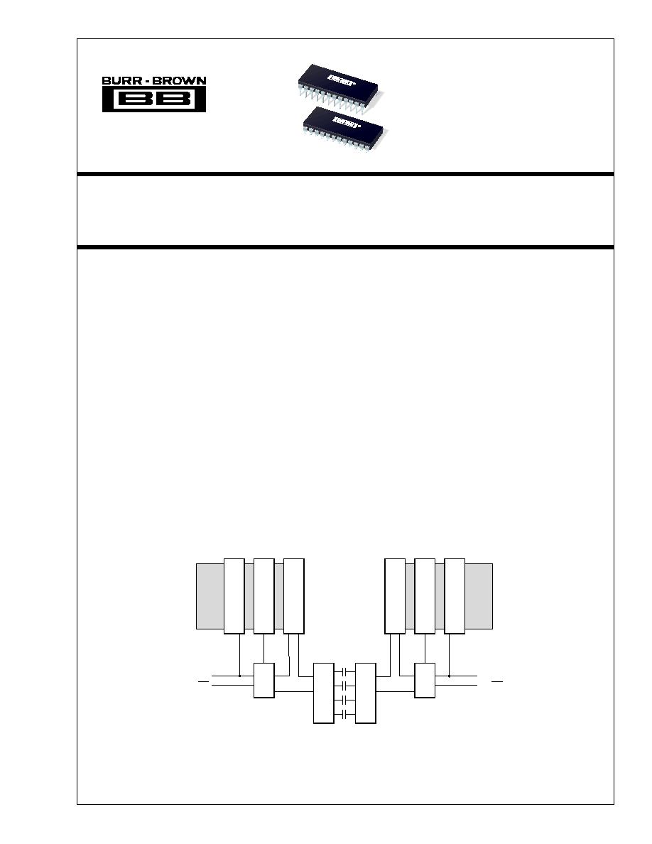
The ISO518 is an 8-channel, isolated, bidirectional
digital coupler based on the Burr-Brown capacitive
barrier technology.
The ISO518 is designed with input and output buffers
for ease of integration into a
µ
P bus system. All data
pins are I/O under the control of the TX pins. Input
and output buffers are controlled by the latch enable
pins. This feature of the ISO518, which allows mul-
tiple access to a data bus, requires extra circuitry when
using an alternative solution.
The ISO518 will transfer an 8-bit word at rates up to
2Mwords/s without the skew problems associated in
implementing this function with optocouplers. The
ISO518 is available in 24-pin PDIP or 24-pin Gull
Wing packages. Both are specified for operation from
40
°
C to +85
°
C.
FEATURES
q
LOW POWER CONSUMPTION:
< 12mW per Channel
q
1500Vrms ISOLATION:
100% Tested by Partial Discharge
q
DOUBLE BUFFERED DESIGN FOR
EASY INTEGRATION INTO BUS-BASED
SYSTEMS
q
TRI-STATE OUTPUTS
q
24-PIN PDIP OR GULL WING PACKAGES
q
2MWORDS/S TRANSFER RATE
APPLICATIONS
q
PARALLEL ADCs/DACs
q
DIGITAL INTERFACES
q
DIGITAL TRANSMISSION
q
GROUND-LOOP ISOLATION
ISO518
®
ISO518
ISO518
©
1998 Burr-Brown Corporation
PDS-1423B
Printed in U.S.A. June, 1999
L
A
T
C
H
DATA
I/O
LEA
ISO518 Functional Block Diagram
TXA/RXA
L
A
T
C
H
S
H
I
F
T
S
H
I
F
T
DATA
I/O
LEB
TXB/RXB
L
A
T
C
H
L
A
T
C
H
International Airport Industrial Park · Mailing Address: PO Box 11400, Tucson, AZ 85734 · Street Address: 6730 S. Tucson Blvd., Tucson, AZ 85706 · Tel: (520) 746-1111
Twx: 910-952-1111 · Internet: http://www.burr-brown.com/ · Cable: BBRCORP · Telex: 066-6491 · FAX: (520) 889-1510 · Immediate Product Info: (800) 548-6132
For most current data sheet and other product
information, visit www.burr-brown.com

2
®
ISO518
ISOLATION
Rated Voltage, Continuous
V
ISO
50Hz, 60Hz
1500
Vrms
Partial Discharge Voltage
1s, 5 x 5pC/cycle
(1)
2500
Vrms
Barrier Impedance
>10
14
|| 10
/pF
Leakage Current
240V, 60Hz
1
µ
A
2500V, 50Hz
12
µ
A
Creepage Distance
PDIP = "P" and "U" Package
11
mm
Internal Isolation Distance
PDIP = "P" and "U" Package
0.1
mm
Transient Recovery Time
5kV/
µ
s Edge
1
µ
s
DC CHARACTERISTICS
High Level Input Voltage
V
IH
See Note 2
2
V
Low Level Input Voltage
V
IL
See Note 2
0.8
V
Input Leakage Current
I
L
5
nA
Input Capacitance
C
IN
5
pF
High Level Output Voltage
V
OH
I
OH
= 6mA
V
S
1
V
Low Level Output Voltage
V
OL
I
OL
= 6mA
0.4
V
Output Short-Circuit Current
I
OS
I
S
, max
30
mA
TIMING
LE Width (LOW)
t
WL
100
ns
LE Width (HIGH)
t
WH
15
ns
Data Set-Up to LEA/B
t
SU
LEA/B HIGH to LOW
0
ns
Data Hold from LEA/B
t
H
LEA/B HIGH to LOW
20
ns
Propagation Delay
t
PD
LEA/B LOW to Data Out
520
ns
Data Output Delay
t
OD
LEO HIGH to Data Out Channels
35
ns
Output Rise and Fall Time
t
RF
10% to 90% Load = 50pF
9
14
ns
Output Enable
t
EN
OE to Data Valid HIGH or LOW
35
ns
Output Disable
t
DIS
OE to Data HI-Z
35
ns
Max Data Transfer Rate
2
Mw/s
Skew
Between Any Two Channels
5
ns
POWER
Supply Voltage
V
SA
, V
SB
Either Side
4.5
5.5
V
Supply Current
I
SA / B
Transmit Side DC
5
10
mA
Transmit Side DC Max Rate
7
15
mA
Supply Current
I
SB /A
Receive Side DC
8
12
mA
Receive Side Max Rate
12
20
mA
TEMPERATURE RANGE
Operating
40
+85
°
C
Storage
40
+125
°
C
Thermal Resistance,
JA
+75
°
C/W
NOTES: (1) All devices receive a 1s test. Failure criterion is > 5pC pulses of
5pC per cycle. (2) Logic inputs are HCT-type and thresholds are a function of power supply
voltage with approximately 400mV hysteresis.
SPECIFICATIONS
At T
A
= +25
°
C, and V
S
= +5V, unless otherwise noted.
The information provided herein is believed to be reliable; however, BURR-BROWN assumes no responsibility for inaccuracies or omissions. BURR-BROWN
assumes no responsibility for the use of this information, and all use of such information shall be entirely at the user's own risk. Prices and specifications are subject
to change without notice. No patent rights or licenses to any of the circuits described herein are implied or granted to any third party. BURR-BROWN does not
authorize or warrant any BURR-BROWN product for use in life support devices and/or systems.
ISO518P, P-U
PARAMETER
CONDITIONS
MIN
TYP
MAX
UNITS
3
®
ISO518
PACKAGE DRAWING
PRODUCT
PACKAGE
NUMBER
(1)
ISO518P
24-Pin Plastic DIP
167
ISO518P-U
24-Pin Gull Wing Surface Mount
167-4
NOTE: (1) For detailed drawing and dimension table, please see end of data
sheet, or Appendix C of Burr-Brown IC Data Book.
1
2
3
4
5
6
7
8
9
10
11
12
V
SA
TXA/RXA
DA0
DA1
DA2
DA3
DA4
DA5
DA6
DA7
LEA
GND
A
GND
B
LEB
DB0
DB1
DB2
DB3
DB4
DB5
DB6
DB7
TXB/RXB
V
SB
24
23
22
21
20
19
18
17
16
15
14
13
ISO518
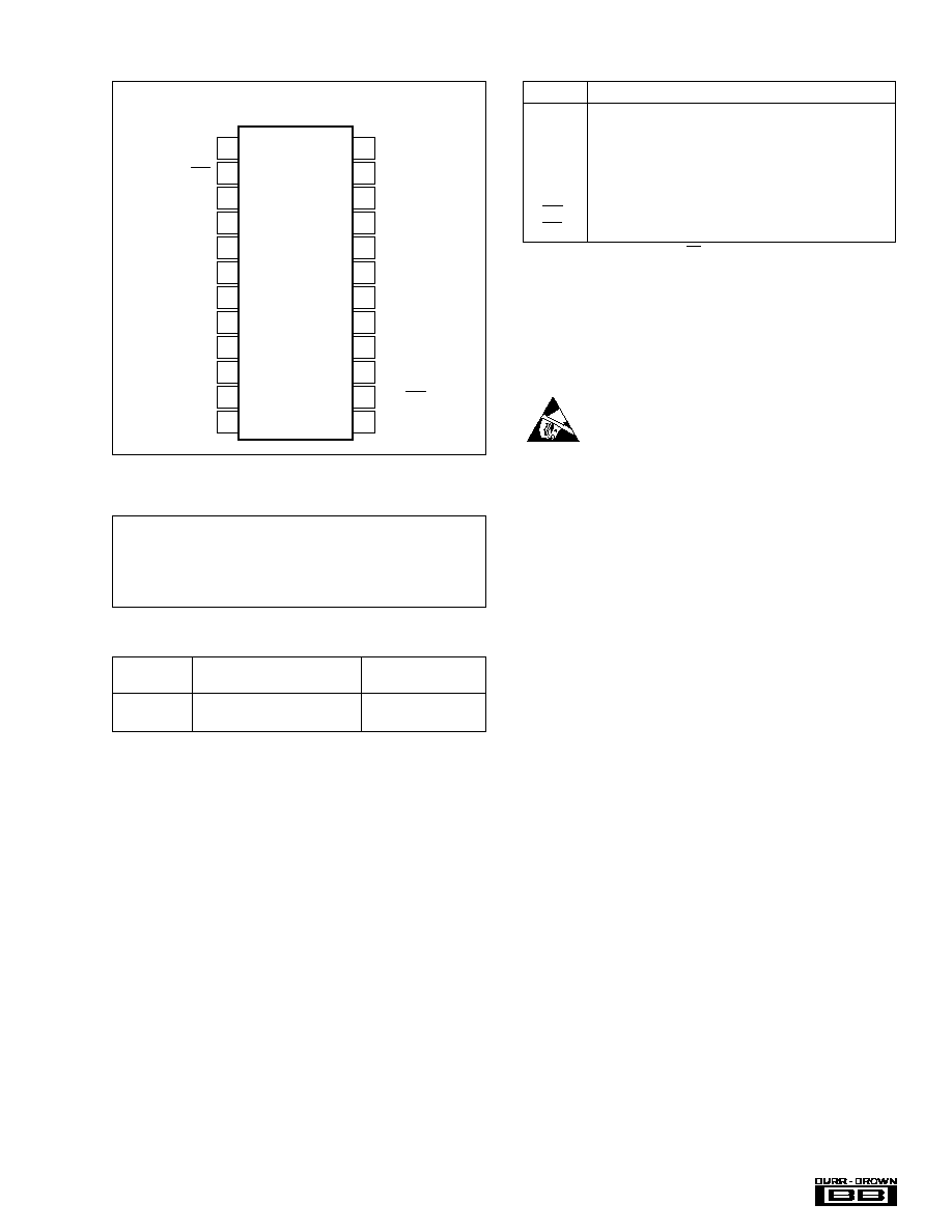
PIN CONFIGURATION
Top View
DIP
NAME
FUNCTION
DA (0 - 7)
Data Bus A. The logic levels on these pins are transmitted
to, or received from the corresponding pins on data bus B.
DB (0 -7)
Data Bus B. The logic levels on these pins are transmitted
to, or received from the corresponding pins on data bus A.
LEA
(1)
Latch Enable A. Latch enable signal for the A data buffer.
LEB
(1)
Latch Enable B. Latch enable signal for the B data buffer.
TX/RXA
(2)
Transmit/Receive Control for Side A.
TX/RXB
(2)
Transmit/Receive Control for Side B.
NOTES: (1) In transmit mode (TX/RX = 1), a logic 0 (LOW) will latch the input
buffer data into the input register and initialize the transmission. A logic 0
(LOW) will latch the internal buffer data into the output register and prevent
any further changes in the output data. A logic 1 (HIGH) will pass the internal
buffer data to the output register and permit each new set of data to appear
as soon as available after transmission. (2) A logic 1 (HIGH) will set that side
to transmit mode and the same side's data bus to input mode. A logic 0 (LOW)
will set that side to receive mode and the same side's data bus to output mode.
FUNCTIONAL DESCRIPTION
ELECTROSTATIC
DISCHARGE SENSITIVITY
Electrostatic discharge can cause damage ranging from per-
formance degradation to complete device failure. Burr-
Brown Corporation recommends that all integrated circuits
be handled and stored using appropriate ESD protection
methods.
ESD damage can range from subtle performance degrada-
tion to complete device failure. Precision integrated circuits
may be more susceptible to damage because very small
parametric changes could cause the device not to meet
published specifications.
ABSOLUTE MAXIMUM RATINGS
Supply Voltage: V
SA
............................................................. 0.5V to +6V
V
SB
............................................................. 0.5V to +6V
Maximum Input Current, Any Input .................................................. 20mA
Continuous Isolation Voltage ..................................................... 1500Vrms
Storage Temperature ...................................................... 40
°
C to +125
°
C
Lead Temperature (soldering, 10s) ................................................. 300
°
C
PACKAGE INFORMATION
4
®
ISO518
OPERATION
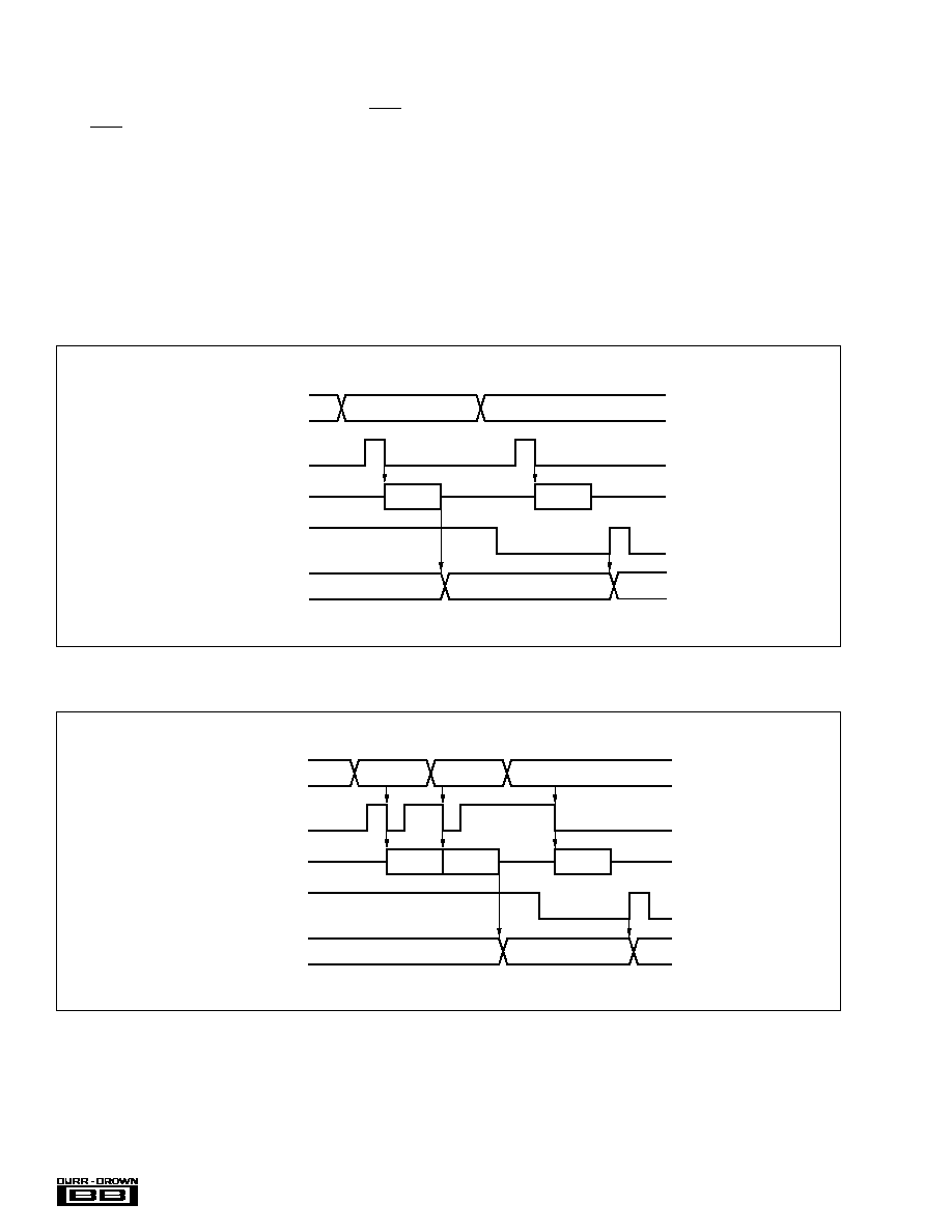
Data is transmitted across the barrier under the control of
LEA or LEB; the direction being decided by TXA/RXA and
TXB/RXB.
Assume side A is set to transmit and side B is set to receive.
With LEA LOW, no data is passed to the input buffer and no
barrier transmission takes place. When LEA is HIGH, the
input data is passed to the input buffer ready for transmission
across the barrier on the falling edge of LEA. On the falling
edge of LEA, the data is latched to prevent any subsequent
input data changes interfering with the single barrier trans-
mission. Should LEA go HIGH again before the transmis-
sion is complete, the data in the input pins will be loaded into
the input buffer without affecting the transmission. How-
ever, should LEA go LOW again before the barrier transmis-
sion is complete, the barrier transmission will terminate and
restart with the new data (see Figure 2). This will not affect
the output data which only changes at the end of a transmis-
sion or under control of LEB.
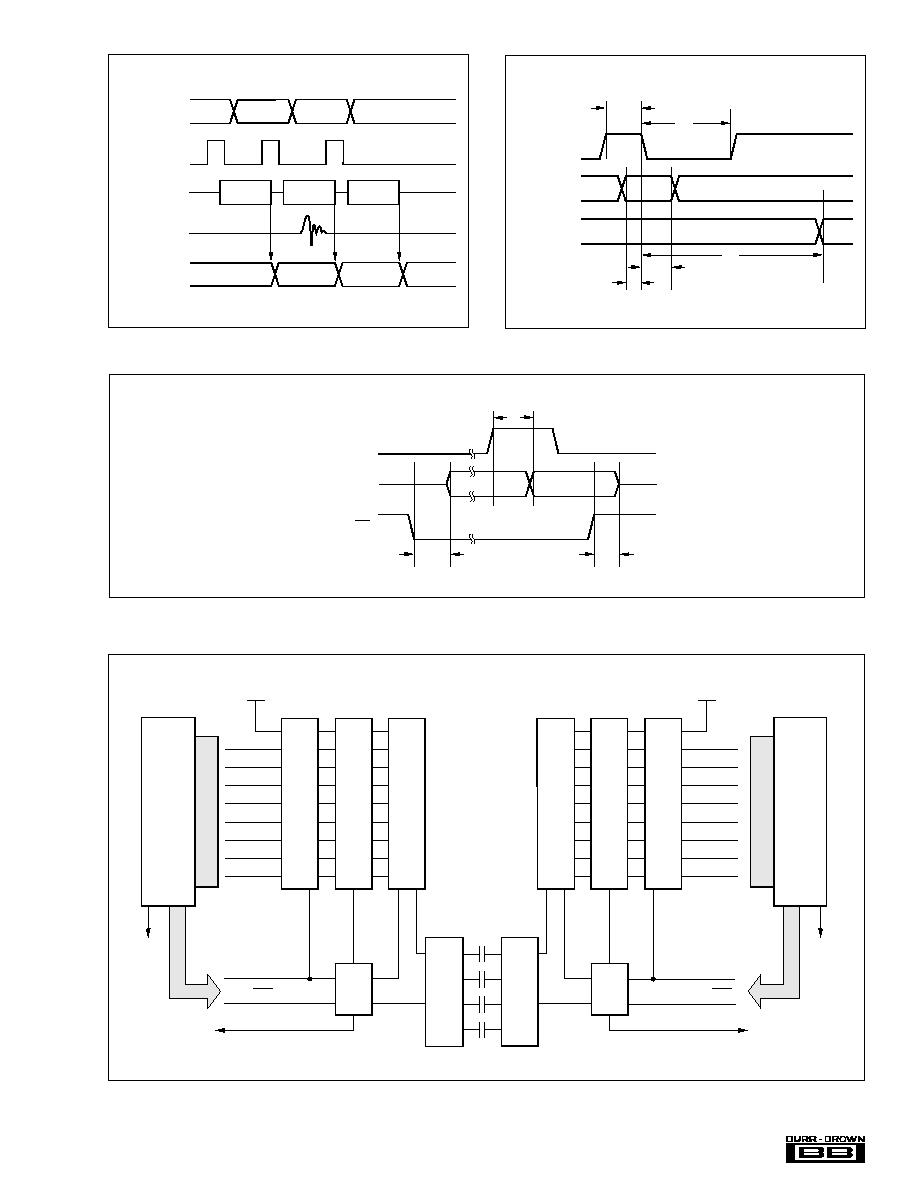
If LEB is HIGH, the output data will change at the end of
transmission. If LEB is LOW the output data will change
when LEB next goes HIGH. In both cases, all data bits will
change together, guaranteeing the specified skew perfor-
mance. It should also be noted that LEB may be used to
ignore transmitted data if required.
FIGURE 1. Data Transfer.
FIGURE 2. Data Transfer--Restart.
n1
DATA BUS: A
LEA
BARRIER
LEB
DATA n
DATA n+1
DATA n1
DATA BUS: B
DATA n
ACTIVE
ACTIVE
n1
DATA BUS: A
LEA
BARRIER
LEB
DATA n+1
DATA n+2
DATA n
DATA n1
DATA BUS: B
DATA +n
ACTIVE
ACTIVE
ACTIVE
5
®
ISO518
n+1
DATA BUS: A
LEA
BARRIER
Transient
DATA n1
DATA n2
DATA n
DATA BUS: B
DATA n+1
Invalid
DATA n-1
ACTIVE
ACTIVE
ACTIVE
FIGURE 3. Data Corruption.
FIGURE 4. Transmission Timing Diagram.
FIGURE 5. Output Data Timing.
FIGURE 6. Burr-Brown I/O System using ISO518.
LEI
TXA/RXA
GND
A
GND
A
S
H
I
F
T
LEB
11
11
2
12
23
14
23
TXB/RXB
24
GND
B
1
3
4
5
6
7
8
9
10
DA0
DA1
DA2
DA3
DA4
DA5
DA6
DA7
V
SA
L
A
T
C
H
D
A
T
A
B
U
S
I/O
A
D
D
R
E
S
S
L
A
T
C
H
S
H
I
F
T
13
22
21
20
19
18
17
16
15
DB0
DB1
DB2
DB3
DB4
DB5
DB6
DB7
V
SB
ISO518
L
A
T
C
H
L
A
T
C
H
GND
B
D
A
T
A
B
U
S
I/O
A
D
D
R
E
S
S
µ
P
µ
P
t
WH
LEA/B
DATA IN
DATA OUT
t
H
t
WL
t
PD
t
SU
DATA OUT
LE
TX/RX
t
OD
t
EN
t
DIS