 | –≠–ª–µ–∫—Ç—Ä–æ–Ω–Ω—ã–π –∫–æ–º–ø–æ–Ω–µ–Ω—Ç: DRV104 | –°–∫–∞—á–∞—Ç—å:  PDF PDF  ZIP ZIP |
Document Outline
- FEATURES
- DESCRIPTION
- APPLICATIONS
- ABSOLUTE MAXIMUM RATINGS
- PACKAGE/ORDERING INFORMATION
- LOGIC BLOCK DIAGRAM
- ELECTRICAL CHARACTERISTICS
- PIN CONFIGURATION
- PIN DESCRIPTIONS
- TYPICAL CHARACTERISTICS
- BASIC OPERATION
- APPLICATIONS INFORMATION
- POWER SUPPLY
- ADJUSTABLE DELAY TIME (INITIAL 100% DUTY CYCLE)
- OSCILLATOR FREQUENCY ADJUST
- ADJUSTABLE DUTY CYCLE (PWM MODE)
- Resistor Controlled Duty Cycle
- Voltage Controlled Duty Cycle
- STATUS OK FLAG
- Over-Current Fault
- Over-Temperature Fault
- PACKAGE MOUNTING
- POWER DISSIPATION
- THERMAL PROTECTION
- HEAT SINKING
- RFI/EMI
- BYPASSING
- APPLICATIONS CIRCUITS
- SINGLE AND MULTICHANNEL
- BEAT FREQUENCIES IN NON-SYNCHRONIZED MULTICHANNEL SYSTEMS
- PEAK SUPPLY CURRENT ELIMINATION - OPTIONAL SWITCHING SKEW

DRV104
SBVS036A ≠ SEPTEMBER 2003 ≠ REVISED NOVEMBER 2003
www.ti.com
DESCRIPTION
The DRV104 is a DMOS, high-side power switch employing
a pulse-width modulated (PWM) output. Its rugged design is
optimized for driving electromechanical devices such as
valves, solenoids, relays, actuators, and positioners. It is also
ideal for driving thermal devices such as heaters, coolers,
and lamps. PWM operation conserves power and reduces
heat rise, resulting in higher reliability. In addition, adjustable
PWM allows fine control of the power delivered to the load.
Time from dc-to-PWM output and oscillator frequency are
externally adjustable.
Separate supply pins for the circuit and driver transistor allow
the output to operate on a different supply than the rest of the
circuit.
The DRV104 can be set to provide a strong initial solenoid
closure, automatically switching to a soft hold mode for
power savings. The duty cycle can be controlled by a
resistor, analog voltage, or a digital-to-analog (D/A) converter
for versatility. The Status OK Flag pin indicates when thermal
shutdown or over-current occurs.
The DRV104 is specified for ≠40
∞
C to +85
∞
C at its case. The
exposed lead frame must be soldered to the circuit board.
FEATURES
q
HIGH OUTPUT DRIVE: 1.2A
q
WIDE SUPPLY RANGE: +8V to +32V
q
COMPLETE FUNCTION:
PWM Output
Adjustable Internal Oscillator: 500Hz to 100kHz
Digitally Controlled Input
Adjustable Delay and Duty Cycle
Over-Current Indicator Flag
q
FULLY PROTECTED:
Thermal Shutdown with Indicator Flag
Internal Current Limit
q
PACKAGE: HTSSOP-14 Surface-Mount PowerPADTM
PRODUCTION DATA information is current as of publication date.
Products conform to specifications per the terms of Texas Instruments
standard warranty. Production processing does not necessarily include
testing of all parameters.
Copyright © 2003, Texas Instruments Incorporated
1.2A PWM High-Side Driver
for Solenoids, Coils, Valves, Heaters, and Lamps
Delay
Adj
Input
On
Off
Thermal Shutdown
Over/Under Current
Status OK
Flag
+V
S
Coil
OUT2
BOOT
Oscillator
V
REF
PWM
Osc Freq
Adj
Duty Cycle
Adj
GND
Delay
DRV104
OUT1
+V
PS
1
+V
PS
2
APPLICATIONS
q
ELECTROMECHANICAL DRIVERS:
Solenoids, Valves, Positioners, Actuators, Relays,
Power Contactor Coils, Heaters, and Lamps
q
FLUID AND GAS FLOW SYSTEMS
q
FACTORY AUTOMATION
q
PART HANDLERS AND SORTERS
q
PHOTOGRAPHIC PROCESSING
q
ENVIRONMENTAL MONITORING AND HVAC
q
THERMOELECTRIC COOLERS
q
MOTOR SPEED CONTROLS
q
SOLENOID PROTECTORS
q
MEDICAL ANALYZERS
Æ
DRV1
04
Please be aware that an important notice concerning availability, standard warranty, and use in critical applications of
Texas Instruments semiconductor products and disclaimers thereto appears at the end of this data sheet.
PowerPAD is a trademark of Texas Instruments. All other trademarks are the property of their respective owners.

DRV104
2
SBVS036A
www.ti.com
Supply Voltage V
S
, V
PS1
, V
PS2
(2)
....................................................... +40V
Input Voltage, Master, SYNC ......................................... ≠0.2V to +5.5V
(3)
PWM Adjust Input .......................................................... ≠0.2V to +5.5V
(3)
Delay Adjust Input .......................................................... ≠0.2V to +5.5V
(3)
Frequency Adjust Input .................................................. ≠0.2V to +5.5V
(3)
Status OK Flag and OUT .................................................... ≠0.2V to V
S
(4)
Boot Voltage ............................................................................... V
S
+ 10V
Operating Temperature Range ...................................... ≠55
∞
C to +125
∞
C
Storage Temperature ..................................................... ≠65
∞
C to +150
∞
C
Junction Temperature .................................................................... +150
∞
C
Lead Temperature (soldering, 10s) ............................................... +300
∞
C
NOTES: (1) Stresses above these ratings may cause permanent damage.
Exposure to absolute maximum conditions for extended periods may de-
grade device reliability. (2) See the Bypass section for discussion about
operating near the maximum supply. (3) Higher voltage may be applied if
current is limited to 2mA. (4) Status OK flag will internally current limit at
about 10mA.
ABSOLUTE MAXIMUM RATINGS
(1)
ELECTROSTATIC
DISCHARGE SENSITIVITY
This integrated circuit can be damaged by ESD. Texas Instru-
ments recommends that all integrated circuits be handled with
appropriate precautions. Failure to observe proper handling
and installation procedures can cause damage.
ESD damage can range from subtle performance degrada-
tion to complete device failure. Precision integrated circuits
may be more susceptible to damage because very small
parametric changes could cause the device not to meet its
published specifications.
SPECIFIED
PACKAGE
TEMPERATURE
PACKAGE
ORDERING
TRANSPORT
PRODUCT
PACKAGE-LEAD
DESIGNATOR
(1)
RANGE
MARKING
NUMBER
MEDIA, QUANTITY
DRV104
PowerPAD HTSSOP-14
PWP
≠40
∞
C to +85
∞
C
DRV104
DRV104PWP
Rails, 90
"
"
"
"
"
DRV104PWPR
Tape and Reel, 2000
NOTE: (1) For the most current specifications and package information, refer to our web site at www.ti.com.
PACKAGE/ORDERING INFORMATION
LOGIC BLOCK DIAGRAM
Delay
Adj
Input
On
Off
Thermal Shutdown
Over Current
Status OK
Flag
+V
S
Coil
OUT2
C
BOOT
Oscillator
1.25V V
REF
PWM
Osc Freq
Adj
Duty Cycle
Adj
GND
Delay
DRV104
OUT1
+V
PS
1
+V
PS
2
C
D
R
PWM
DMOS
DMOS
2.75 ∑ I
REF
R
FREQ
I
REF
13
10
11
5
1
3
14
SYNC
12
Master
4
2
8
9
6
7

DRV104
3
SBVS036A
www.ti.com
ELECTRICAL CHARACTERISTICS
At T
C
= +25
∞
C, V
S
= V
PS
= +24V, Load = 100
, 4.99k
Status OK flag pull-up to +5V, Boot capacitor = 470pF, Delay Adj Capacitor (C
D
) = 100pF to GND, Osc
Freq Adj Resistor = 191k
to GND, Duty Cycle Adj Resistor = 147k
to GND, and Master and SYNC open, unless otherwise noted.
DRV104
PARAMETER
CONDITIONS
MIN
TYP
MAX
UNITS
OUTPUT
Output Saturation Voltage, Source
I
O
= 1A
+0.45
+0.65
V
I
O
= 0.1A
+0.05
+0.07
V
Current Limit
(1)(7)
1.2
2.0
2.6
A
Leakage Current
DMOS Output Off, V
PS
= V
S
= 32V
1
10
µ
A
DELAY TO PWM
(3)
DC to PWM Mode
Delay Equation
(4)
Delay to PWM
C
D
∑ 10
6
(C
D
in F ∑ 1.24)
s
Delay Time
C
D
= 0.1
µ
F
60
80
100
ms
Minimum Delay Time
(5)
C
D
= 0
18
µ
s
DUTY CYCLE ADJUST
Duty Cycle Range
10 to 90
%
Duty Cycle Accuracy
50% Duty Cycle, 25kHz
±
2
±
5
%
vs Supply Voltage
50% Duty Cycle, V
S
= V
PS
= 8V to 32V
±
2
%
Nonlinearity
(6)
10% to 90% Duty Cycle
1
% FSR
DYNAMIC RESPONSE
Output Voltage Rise Time
V
O
= 10% to 90% of V
PS
1
2
µ
s
Output Voltage Fall Time
V
O
= 90% to 10% of V
PS
0.2
2
µ
s
SYNC Output Rise Time
V
SYNC
= 10% to 90%
0.5
2
µ
s
SYNC Output Fall Time
V
SYNC
= 10% to 90%
0.5
2
µ
s
Oscillator Frequency Range
External Adjust
0.5 to 100
kHz
Oscillator Frequency Accuracy
R
FREQ
= 191k
20
25
30
kHz
STATUS OK FLAG
Normal Operation
20k
Pull-Up to +5V
+4.5
+5
V
Fault
(7)
4.99k
Pull-Up to +5V
+0.45
+0.6
V
Over-Current Flag: Set--Delay
5
µ
s
INPUT
(2)
V
INPUT
Low
0
+1.2
V
V
INPUT
High
+2.2
+5.5
V
I
INPUT
Low (output disabled)
V
INPUT
= 0V
0.01
1
µ
A
I
INPUT
High (output enabled)
V
INPUT
= +4.5V
0.01
1
µ
A
Propagation Delay
On to Off and Off to On, INPUT to OUT
2.2
µ
s
(master mode)
On to Off and Off to On, INPUT to SYNC
0.4
µ
s
MASTER INPUT
V
MSTR
Low
0
+1.2
V
V
MSTR
High
+2.2
+5.5
V
I
MSTR
Low (slave mode)
V
INPUT
= 0V
15
25
µ
A
I
MSTR
High (master mode)
V
INPUT
= +4.5V
15
25
µ
A
SYNC INPUT
V
SYNC
Low
0
+1.2
V
V
SYNC
High
+2.2
+5.5
V
I
MSTR
Low (OUT disabled in slave mode)
V
INPUT
= 0V
0.01
1
µ
A
I
MSTR
High (OUT disabled in slave mode)
V
INPUT
= +4.5V
0.01
1
µ
A
Propagation Delay
On to Off and Off to On, SYNC to OUT (slave)
2.2
µ
s
SYNC OUTPUT
(9)
V
OL
Sync
I
SYNC
= 100
µ
A (sinking)
0.1
0.3
V
V
OH
Sync
I
SYNC
= 100
µ
A (sourcing)
+4.0
+4.2
V
THERMAL SHUTDOWN
Junction Temperature
Shutdown
+160
∞
C
Reset from Shutdown
+140
∞
C
POWER SUPPLY
Specified Operating Voltage
+24
V
Operating Voltage Range
+8
+32
V
Quiescent Current (V
S
)
I
O
= 0
0.6
1
mA
TEMPERATURE RANGE
Specified Range
≠40
+85
∞
C
Operating Range
≠55
+125
∞
C
Storage Range
≠65
+150
∞
C
Thermal Resistance,
JA
(8)
HTSSOP-14 with PowerPAD
37.5
∞
C/W
NOTES: (1) Output current resets to zero when current limit is reached. (2) Logic high enables output (normal operation). (3) Constant dc output to PWM (Pulse-
Width Modulated) time. (4) Maximum delay is determined by an external capacitor. Pulling the Delay Adjust Pin low corresponds to an infinite (continuous) delay.
(5) Connecting the Delay Adjust pin to +5V reduces delay time to 3
µ
s. (6) V
IN
at pin 1 to percent of duty cycle at pins 6 and 7. (7) Flag indicates fault from over-
temperature or over-current conditions. (8)
JA
= 37.5
∞
C/W measured on JEDEC standard test board.
JC
= 2.07
∞
C/W. (9) SYNC output follows power output in
master mode. Power output follows SYNC input in slave mode.

DRV104
4
SBVS036A
www.ti.com
PIN
NAME
DESCRIPTION
1
Duty Cycle Adjust
Internally, this pin connects to the input of a comparator and a (2.75 x I
REF
) current source from V
S
. The voltage at this node linearly
sets the duty cycle. The duty cycle can be programmed with a resistor, analog voltage, or the voltage output of a D/A converter. The
active voltage range is from 1.3V to 3.9V to facilitate the use of single-supply control electronics. At 3.56V, the output duty cycle is
near 90%. At 1.5V, the output duty cycle is near 10%. Internally, this pin is forced to 1.24V. No connection is required when the device
is in slave mode.
2
Delay Adjust
This pin sets the duration of the initial 100% duty cycle before the output goes into PWM mode. Leaving this pin floating results in
a delay of approximately 18
µ
s, which is internally limited by parasitic capacitance. Minimum delay may be reduced to less than 3
µ
s
by tying the pin to 5V. This pin connects internally to a 15
µ
A current source from V
S
and to a 2.6V threshold comparator. When the
pin voltage is below 2.6V, the output device is 100% On. The PWM oscillator is not synchronized to the Input (pin 1), so the duration
of the first pulse may be any portion of the programmed duty cycle. No connection is required when the device is in slave mode.
3
Oscillator
PWM frequency is adjustable. A resistor to ground sets the current I
REF
and the internal PWM oscillator frequency. A range of 500Hz
Frequency Adjust
to 100kHz can be achieved with practical resistor values. Although oscillator frequency operation below 500Hz is possible, resistors
higher than 10M
will be required. The pin then becomes a very high-impedance node and is, therefore, sensitive to noise pickup
and PCB leakage currents. Resistor connection to this pin in slave mode sets the frequency at which current limit reset occurs.
4
Master
With no connection, this pin is driven to 5V by an internal 15
µ
A current source. In this mode the device is the master and the SYNC
pin becomes a 0V to 4.2V output, which is High when the power device is on. When the Master/Input is 0V, the SYNC pin is an
input. In slave mode, the output follows the SYNC pin; the output is High when SYNC is High.
5
BOOT
The bootstrap capacitor between this pin and the output, supplies the charge to provide the V
GS
necessary to turn on the power
device. C
BOOT
should be larger than 100pF. Use of a smaller C
BOOT
may slow the output rise time, device is specified and tested
with 470pF.
6, 7
OUT1, OUT2
The output is the source of a power DMOS transistor with its drain connected to V
PS
. Its low on-resistance (0.45
typ) assures
low power dissipation in the DRV104. Gate drive to the power device is controlled to provide a slew-rate limited rise-and-fall time.
This reduces the radiated RFI/EMI noise. A flyback diode is needed with inductive loads to conduct the load current during the off
cycle. The external diode should be selected for low forward voltage and low storage time. The internal diode should not be used
as a flyback diode. If devices are connected in parallel, the outputs must be connected through individual diodes. Devices are
current-limit protected for shorts to ground, but not to supply.
8, 9
V
PS
1, V
PS
2
These are the load power-supply pins to the drain of the power device. The load supply voltage may exceed the voltage at pin 10
by 5V, but must not exceed 37V.
10
+V
S
This is the power-supply connection for all but the drain of the power device. The operating range is 8V to 32V.
11
GND
This pin must be connected to the system ground for the DRV104 to function. It does not carry the load current when the power
DMOS device is switched on.
12
SYNC
The SYNC pin is a 0V to 4.2V copy of the output when the Master/Slave pin is High. As an output, it can supply 100
µ
A with 1k
output resistance. At 2mA, it current limits to either 4.2V or 0V. When the Master pin is Low, it is an input and the threshold is 2V.
SYNC output follows power output in master mode, and is not affected by thermal or current-limit shutdown. Power output follows
SYNC input in slave mode.
13
Status OK Flag
Normally High (active Low), a Flag Low signals either an over-temperature or over-current fault. A thermal fault (thermal shutdown)
occurs when the die surface reaches approximately 160
∞
C and latches until the die cools to 140
∞
C. This output requires a pull-
up resistor and it can typically sink 2mA, sufficient to drive a low-current LED. Sink current is internally limited at 10mA, typical.
14
Input
The input is compatible with standard TTL levels. The device becomes enabled when the input voltage is driven above the typical
switching threshold, 1.8V; below this level, the device is disabled. Input current is typically 1
µ
A when driven High and 1
µ
A when driven
Low. The input should not be directly connected to the power supply (V
S
) or damage will occur.
PIN DESCRIPTIONS
PIN CONFIGURATION
Top View
HTSSOP
Duty Cycle Adj
Delay Adj
Osc Freq Adj
Master
Boot
OUT1
OUT2
Input
Status OK Flag
SYNC
GND
+V
S
V
PS
1
V
PS
2
1
2
3
4
5
6
7
14
13
12
11
10
9
8
DRV104
PowerPAD
Duty Cycle Adj
Delay Adj
Osc Freq Adj
GND
Input
Status OK Flag
+V
S
OUT
1
3
5
7
14
12
10
8
DRV103
PowerPAD
DRV103 for Reference
Top View
SO

DRV104
5
SBVS036A
www.ti.com
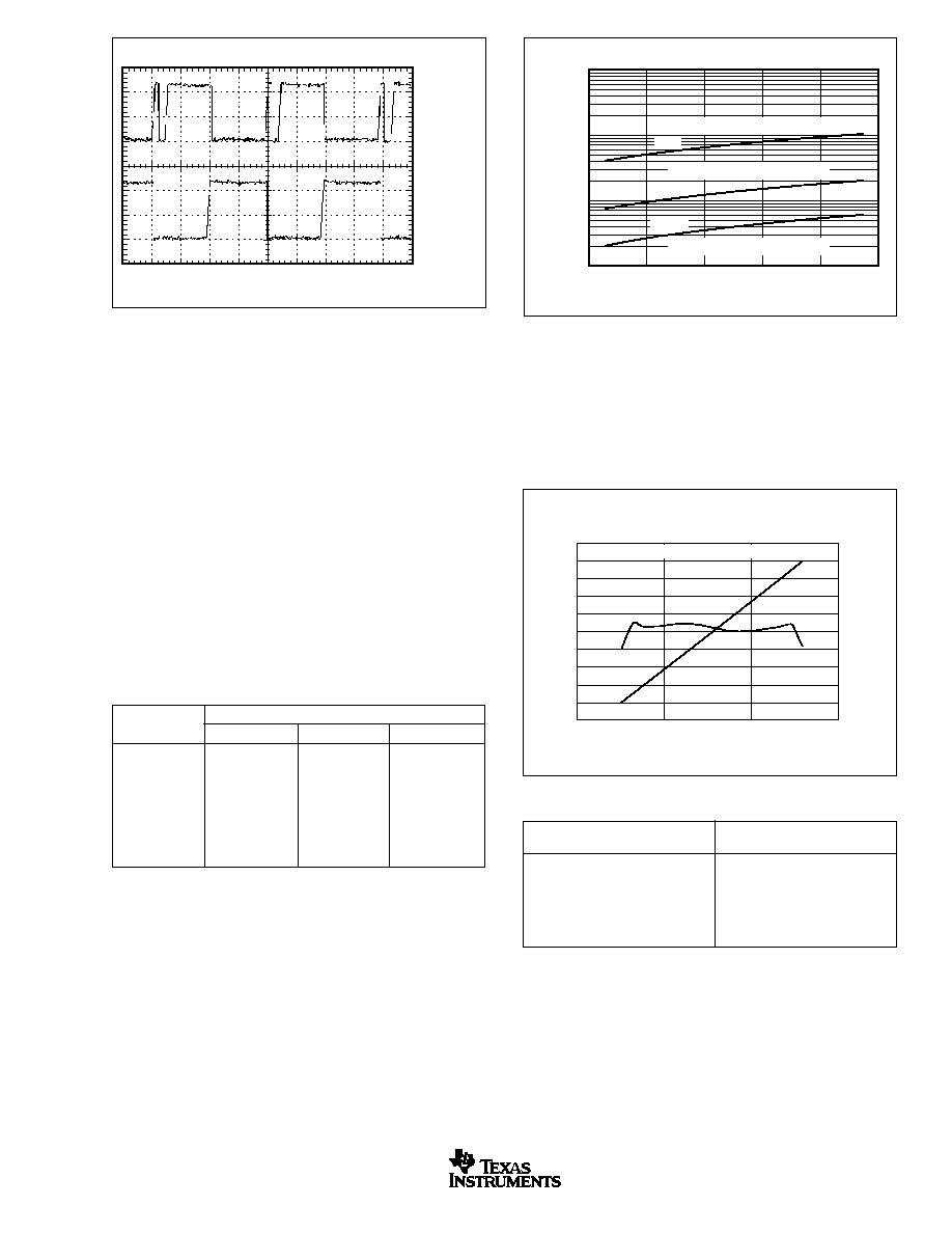
TYPICAL CHARACTERISTICS
At T
C
= +25
∞
C and V
S
= +24V, unless otherwise noted.
V
OUT
AND I
SOLENOID
WAVEFORMS WITH SOLENOID LOAD
2
1
0
I
SOLENOID
(A)
50
Time (ms)
100
0
Input
V
OUT
0
0
PWM Mode
pull-in
ON
drop-out
+V
S
V
OUT
AND I
OUT
WAVEFORMS WITH RESISTIVE LOAD
2
1
0
I
OUT
(A)
50
Time (ms)
100
0
+V
S
0
0
+V
S
R
L
PWM Mode
I
AVG
ON
CURRENT LIMIT SHUTDOWN WAVEFORMS
5
0
24
0
24
0
V
IN
(V)
V
OUT
(V)
50
Time (
µ
s)
100
0
V
IN
V
OUT
Status
OK
Flag
Off
Off
On
OK
OK
OK
OK
OK
OK
OK
0.70
0.65
0.60
0.55
0.50
0.45
0.40
≠10
≠60
Current (mA)
40
90
140
QUIESCENT CURRENT vs TEMPERATURE
Temperature (
∞
C)
8V
12V
32V
24V
88
86
84
82
80
78
≠10
≠60
Delay (ms)
40
90
140
DELAY TO PWM vs TEMPERATURE
Temperature (
∞
C)
24V
12V, 8V
32V
C
D
= 0.1
µ
F
2.5
2.3
2.1
1.9
1.7
1.5
1.3
≠10
≠60
Current Limit (A)
40
90
140
CURRENT LIMIT SHUTDOWN vs TEMPERATURE
Temperature (
∞
C)

DRV104
6
SBVS036A
www.ti.com
TYPICAL CHARACTERISTICS
(Cont.)
At T
C
= +25
∞
C and V
S
= +24V, unless otherwise noted.
14
13
12
11
10
9
8
7
6
≠60
Minimum Delay (
µ
s)
40
140
MINIMUM DELAY vs JUNCTION TEMPERATURE
Temperature (
∞
C)
32V
24V
12V
8V
C
D
= 0pF
26.0
25.5
25.0
24.5
24.0
≠10
≠60
Frequency (kHz)
40
90
140
OSCILLATOR FREQUENCY
vs JUNCTION TEMPERATURE
Temperature (
∞
C)
24V
12V
12V
32V
R
FREQ
= 191k
53
52
51
50
49
48
47
≠60
Duty Cycle (%)
40
8V
140
DUTY CYCLE vs JUNCTION TEMPERATURE
Temperature (
∞
C)
12V
24V
32V
R
PWM
= 147k
0.8
0.6
0.4
0.2
0
≠10
≠60
V
SA
T
at 1
Amp (V)
40
90
140
V
SAT
vs JUNCTION TEMPERATURE
Temperature (
∞
C)
1.250
1.249
1.248
1.247
1.246
1.245
1.244
≠10
≠60
V
REF
(V)
40
90
140
V
REF
vs TEMPERATURE
Temperature (
∞
C)
8V
12V
24V
32V
250
200
150
100
50
0
4
Input Current (
µ
A)
5
6
INPUT CURRENT vs INPUT VOLTAGE
Input Voltage (V)

DRV104
7
SBVS036A
www.ti.com
FIGURE 1. DRV104 Basic Circuit Connections.
BASIC OPERATION
The DRV104 is a high-side, DMOS power switch employing
a PWM output for driving electromechanical and thermal
devices. Its design is optimized for two types of applications:
as a 2-state driver (open/close) for loads such as solenoids
and actuators; and a linear driver for valves, positioners,
heaters, and lamps. Its low 0.45
On resistance, small size,
adjustable delay to PWM mode, and adjustable duty cycle
make it suitable for a wide range of applications.
Figure 1 shows the basic circuit connections to operate the
DRV104. A 1
µ
F (10
µ
F when driving high current loads) or
larger ceramic bypass capacitor is recommended on the
power-supply pin.
Control input (pin 14) is level-triggered and compatible with
standard TTL levels. An input voltage between +2.2V and
+5.5V turns the device's output On, while a voltage of 0V to
+1.2V shuts the DRV104's output Off. Input bias current is
typically 1
µ
A. Delay Adjust (pin 2) and Duty Cycle Adjust
(pin 1) allow external adjustment of the PWM output signal.
The Delay Adjust pin can be left floating for minimum delay
to PWM mode (typically 18
µ
s) or a capacitor can be used
to set a longer delay time. A resistor, analog voltage, or a
voltage from a D/A converter can be used to control the duty
cycle of the PWM output. The D/A converter must be able
to sink a current of 2.75 ∑ I
REF
(I
REF
= V
REF
/R
FREQ
).
Figure 2 illustrates a typical timing diagram with the Delay
Adjust pin connected to a 4.7nF capacitor, the duty cycle set
to 75%, and oscillator frequency set to 1kHz. See the
Adjustable and Adjustable Delay Time section for equations
and further explanation. Ground (pin 11) must be connected
to the system ground for the DRV104 to function. The load
(relay, solenoid, valve, etc.) should be connected between
the ground and the output (pins 6, 7). For an inductive load,
an external flyback diode is required, as shown in Figure 1.
The diode maintains continuous current flow in the inductive
load during Off periods of PWM operation. For remotely
located loads, the external diode is ideally located next to the
DRV104. The internal ESD clamp diode between the output
and ground is not intended to be used as a "flyback diode."
The Status OK Flag (pin 13) provides fault status for over-
current and thermal shutdown conditions. This pin is active
Low with an output voltage of typically +0.48V during a fault
condition.
Delay
Adj
C
D
R
PWM
TTL IN
Relay
C
BOOT
(2)
+V
S
GND
OUT
+V
S
Status
OK Flag
3A
Flyback
Diode
(1)
+8V to +32V
Osc Freq
Adj
Duty Cycle
Adj
R
FREQ
(3)
DRV104
11
5
1
3
2
14
6, 7
10
13
V
PS
8, 9
R
LED
LED
OK = LED On
2mA
1
µ
F
+
NOTES: (1) Motorola MSRS1100T3 (1A, 100V),
Motorola MBRS360T3 (3A, 60V), or Microsemi SK34MS (3A, 40V).
(2) Performance specified with C
BOOT
= 470pF. (3) When switching a
high-load current, a 100pF capacitor in parallel with R
FREQ
is
recommended to maintain a clean output switching waveform
and duty cycle, see Figure 5.
T
OFF
T
ON
On
Off
Off
Period =
= T
ON
+ T
OFF
1
FREQ
Duty Cycle =
T
ON
T
ON
+ T
OFF
Delay Time
+V
S
V
O
(V)
0
+V
S
/R
L
I
O
(A)
0
TTL High
Input (V)
TTL Low
0
1
2
3
4
Time (ms)
5
6
7
8
9
FIGURE 2. Typical Timing Diagram.

DRV104
8
SBVS036A
www.ti.com
INITIAL CONSTANT
OUTPUT DURATION
C
D
3
µ
s
Pin 2 Tied to +5V
18
µ
s
Pin 2 Open
81
µ
s
100pF
0.81ms
1nF
8.1ms
10nF
81ms
100nF
0.81s
1
µ
F
8.1s
10
µ
F
TABLE I. Delay Adjust Times.
FIGURE 3. Simplified Delay Adjust and Frequency Adjust Inputs.
FIGURE 4. Using a Resistor to Program Oscillator Frequency.
OSCILLATOR FREQUENCY
R
FREQ
(nearest 1% values)
(Hz)
(
)
100k
47.5k
50k
100k
25k
191k
10k
499k
5k
976M
500
10M
TABLE II. Oscillator Frequency Resistance.
APPLICATIONS INFORMATION
POWER SUPPLY
The DRV104 operates from a single +8V to +32V supply with
excellent performance. Most behavior remains unchanged
throughout the full operating voltage range. Parameters that
vary significantly with operating voltage are shown in the
Typical Characteristics.
ADJUSTABLE DELAY TIME
(INITIAL 100% DUTY CYCLE)
A unique feature of the DRV104 is its ability to provide an initial
constant DC output (100% duty cycle) and then switch to
PWM mode output to save power. This function is particularly
useful when driving solenoids that have a much higher pull-in
current requirement than continuous-hold requirement.
The duration of this constant DC output (before PWM output
begins) can be externally controlled by a capacitor con-
nected from Delay Adjust (pin 2) to ground according to
Equation 1:
Delay Time
(C
D
∑ 10
6
)/1.24
(1)
(time in seconds, C
D
in Farads)
Leaving the Delay Adjust pin open results in a constant output
time of approximately 18
µ
s. The duration of this initial output
can be reduced to less than 3
µ
s by connecting the pin to 5V.
Table I provides examples of delay times (constant output
before PWM mode) achieved with selected capacitor values.
The internal Delay Adjust circuitry is composed of a 3
µ
A
current source and a 2.6V comparator, as shown in Figure 3.
Thus, when the pin voltage is less than 2.6V, the output
device is 100% On (DC output mode).
OSCILLATOR FREQUENCY ADJUST
The DRV104 PWM output frequency can be easily pro-
grammed over a wide range by connecting a resistor (R
FREQ
)
between Osc Freq Adj (pin 3) and ground. A range of 500Hz
to 100kHz can be achieved with practical resistor values, as
shown in Table II. Refer to the PWM Frequency vs R
FREQ
plot
shown in Figure 4 for additional information. Although oscilla-
tor frequency operation below 500Hz is possible, resistors
higher than 10M
will be required. The pin becomes a very
high impedance node and is therefore sensitive to noise
3
µ
A
C
D
R
FREQ
V
REF
I
REF
+V
S
V
REF
Reset
+2.6V
+1.25V
Input
1000M
100M
10M
1M
100k
10k
1k
100
1k
10
R
FREQ
(
)
10k
100k
1M
PWM FREQUENCY vs R
FREQ
Frequency (Hz)
R
FREQ
k
( )
=
1
1.4518
◊
10
-
6
+
2.0593
◊
10
-
7
◊
F Hz
( )
When switching a high-load current, 100pF capacitors in
parallel with R
FREQ
are recommended to maintain a clean
output switching waveform and duty cycle, see Figure 5.
pickup and PCB leakage currents if very high resistor values
are used. Refer to Figure 3 for a simplified circuit of the
frequency adjust input.
The DRV104's adjustable PWM output frequency allows it to
be optimized for driving virtually any type of load.
DRV104
9
SBVS036A
www.ti.com
DUTY CYCLE
R
PWM
(
) (Nearest 1% Values)
(%)
5kHz
25kHz
100kHz
10
412k
84.5k
25.5k
20
487k
97.6k
28.7k
30
562k
113k
31.6k
40
649k
130k
35.7k
50
715k
147k
39.2k
60
787k
162k
43.2k
70
887k
174k
44.9k
80
953k
191k
--
90
1050k
205k
--
FIGURE 6. Using a Resistor to Program Duty Cycle.
FIGURE 5. Output Waveform at High Load Current.
FIGURE 7. Using a Voltage to Program Duty Cycle.
DUTY CYCLE
V
PWM
(%)
(V)
10
1.501
20
1.773
40
2.296
60
2.813
80
3.337
90
3.589
TABLE IV. Duty Cycle Adjust Voltage.
TABLE III. Duty Cycle Adjust Resistance.
ADJUSTABLE DUTY CYCLE (PWM MODE)
The DRV104's externally adjustable duty cycle provides an
accurate means of controlling power delivered to a load.
Duty cycle can be set over a range of 10% to 90% with an
external resistor, analog voltage, or the voltage output of a
D/A converter. A low duty cycle results in reduced power
dissipation in the load. This keeps the DRV104 and the load
cooler, resulting in increased reliability for both devices.
Resistor Controlled Duty Cycle
Duty cycle is easily programmed by connecting a resistor
(R
PWM
) between Duty Cycle Adjust (pin 1) and ground. High
resistor values correspond to high duty cycles. At 100kHz,
the range of adjustable duty cycle is limited to 10% to 70%.
Table III provides resistor values for typical duty cycles.
Resistor values for additional duty cycles can be obtained
from Figure 6.
Voltage Controlled Duty Cycle
The duty cycle can also be programmed by analog voltage
V
PWM
. With V
PWM
3.59V, the duty cycle is about 90%.
Decreasing this voltage results in decreased duty cycles. Table
IV provides V
PWM
values for typical duty cycles. Figure 7 shows
the relationship of duty cycle versus V
PWM
and its linearity.
10M
1M
100k
10k
20
40
0
R
PWM
(
)
60
80
100
DUTY CYCLE vs R
PWM
Duty Cycle (%)
5kHz
25kHz
100kHz
R
PWM
(k
) = 334.35 + 7.75(%DC)
R
PWM
(k
) = 68.73 + 1.52(%DC)
R
PWM
(k
) = 20.62 + 0.39(%DC)
R
FREQ
only
With
100pF in
Parallel
with R
FREQ
Time (10
µ
s)
100
90
80
70
60
50
40
30
20
10
0
2
1
Duty Cycle (%)
2.0
1.5
1.0
0.5
0
≠0.5
≠1.0
≠1.5
≠2.0
Duty Cycle Error (%)
3
4
DUTY CYCLE AND DUTY CYCLE ERROR
vs VOLTAGE
V
PWM
(V)
Duty Cycle
Duty Cycle Error
At V
S
= 24V and F = 25kHz: V
PWM
= 1.25 + 0.026
◊
%DC

DRV104
10
SBVS036A
www.ti.com
FIGURE 9. Non-Latching Fault Monitoring Circuit.
FIGURE 10. Latching Fault Monitoring Circuit.
FIGURE 11. Using an LED to Indicate a Fault Condition.
FIGURE 8. Simplified Duty Cycle Adjust Input.
The Duty Cycle Adjust pin is internally driven by an oscillator
frequency dependent current source and connects to the
input of a comparator, as shown in Figure 8. The DRV104's
PWM adjustment is inherently monotonic; that is, a de-
creased voltage (or resistor value) always produces an
decreased duty cycle.
STATUS OK FLAG
The Status OK Flag (pin 13) provides a fault indication for
over-current and thermal shutdown conditions. During a fault
condition, the Status OK Flag output is driven Low (pin
voltage typically drops to 0.45V). A pull-up resistor, as shown
in Figure 9, is required to interface with standard logic. Figure
9 also gives an example of a non-latching fault monitoring
circuit, while Figure 10 provides a latching version. The
Status OK Flag pin can sink up to 10mA, sufficient to drive
external logic circuitry, a reed relay, or an LED (as shown in
Figure 11) to indicate when a fault has occurred. In addition,
the Status OK Flag pin can be used to turn off other
DRV104s in a system for chain fault protection.
Over-Current Fault
An over-current fault occurs when the PWM peak output
current is greater than typically 2.0A. The Status OK flag is
not latched. Since current during PWM mode is switched on
and off, the Status OK flag output will be modulated with
PWM timing (see the Status OK flag waveforms in the
Typical Characteristics).
Avoid adding capacitance to pins 6, 7 (OUT) because this
can cause momentary current limiting.
Over-Temperature Fault
A thermal fault occurs when the die reaches approximately
160
∞
C, producing an effect similar to pulling the input low.
Internal shutdown circuitry disables the output. The Status
OK Flag is latched in the Low state (fault condition) until the
die has cooled to approximately 140
∞
C.
2.75 ∑ I
REF
R
PWM
+V
S
OSC
3.9V
1.3V
13
20k
+5V
Q
Q
CLR
OK
OK
OK Reset
J
CLK
GND
K
V
S
74XX76A
(1)
NOTE: (1) A small capacitor (10pF) may be required in noisy environments.
DRV104
Thermal Shutdown
Over-Current
8, 9
V
PS
6, 7
OUT
PWM
Status OK Flag
5k
+5V
Status OK Flag
(LED)
HLMP-Q156
13
DRV104
Thermal Shutdown
Over-Current
6, 7
8, 9
V
PS
OUT
PWM
DRV104
Thermal Shutdown
Over-Current
PWM
6, 7
8, 9
13
OUT
V
PS
5k
Pull-Up
+5V
Status OK Flag
TTL or HCT

DRV104
11
SBVS036A
www.ti.com
FIGURE 12. Recommended PCB Layout.
FIGURE 13. PowerPAD Heat Transfer.
FIGURE 14. Heat-Sink Thermal Resistance vs PCB Copper
Area.
PACKAGE MOUNTING
Figure 12 provides recommended printed circuit board (PCB)
layouts for the PowerPAD HTSSOP-14 package. The metal
pad of the PowerPAD HTSSOP-14 package is electrically
isolated from other pins and ideally should be connected to
a ground. For reliable operation, the PowerPAD must be
directly soldered to a circuit board, as shown in Figure 13.
Increasing the heat-sink copper area improves heat dissipa-
tion. Figure 14 shows typical junction-to-ambient thermal
resistance as a function of the PCB copper area.
POWER DISSIPATION
The DRV104 power dissipation depends on power supply,
signal, and load conditions. Power dissipation (P
D
) is equal to
the product of output current times the voltage across the
conducting DMOS transistor times the duty cycle. Using the
lowest possible duty cycle necessary to assure the required
hold force can minimize power dissipation in both the load and
in the DRV104. At 1A, the output DMOS transistor on-resis-
tance is 0.45
, increasing to 0.65
at current limit.
Solder Attachment
to PCB
2.0
2.0
2.4
0.65
0.0
1.0
2.0
3.5
(all dimensions in mm)
Copper Traces
Signal Trace
Copper Pad
Thermal Vias
DRV104 Die
Pad-to-Board
Solder
THERMAL RESISTANCE vs
PCB COPPER AREA
80
70
60
50
40
30
Thermal Resistance,
JA
(
∞
C/W)
0
1
2
3
4
5
Copper Area (inches
2
)
DRV104
PowerPAD
Surface-Mount Package
1oz. Copper

DRV104
12
SBVS036A
www.ti.com
At very high oscillator frequencies, the energy in the DRV104's
linear rise and fall times can become significant and cause
an increase in P
D.
THERMAL PROTECTION
Power dissipated in the DRV104 causes its internal junction
temperature to rise. The DRV104 has an on-chip thermal
shutdown circuitry that protects the IC from damage. The
thermal protection circuitry disables the output when the
junction temperature reaches approximately +160
∞
C, allow-
ing the device to cool. When the junction temperature cools
to approximately +140
∞
C, the output circuitry is again en-
abled. Depending on load and signal conditions, the thermal
protection circuit may cycle on and off. This limits the dissi-
pation of the driver but may have an undesirable effect on the
load.
Any tendency to activate the thermal protection circuit indi-
cates excessive power dissipation or an inadequate heat
sink. For reliable operation, junction temperature should be
limited to a maximum of +125
∞
C. To estimate the margin of
safety in a complete design (including heat-sink), increase
the ambient temperature until the thermal protection is trig-
gered. Use worst-case load and signal conditions. For good
reliability, thermal protection should trigger more than 35
∞
C
above the maximum expected ambient condition of your
application. This produces a junction temperature of 125
∞
C
at the maximum expected ambient condition.
The internal protection circuitry of the DRV104 is designed to
protect against overload conditions. It is not intended to
replace proper heat sinking. Continuously running the DRV104
into thermal shutdown will degrade device reliability.
HEAT SINKING
Most applications do not require a heat-sink to assure that
the maximum operating junction temperature (125
∞
C) is not
exceeded. However, junction temperature should be kept as
low as possible for increased reliability. Junction temperature
can be determined according to the following equations:
T
J
= T
A
+ P
D
JA
(3)
JA
=
JC
+
CH
+
HA
(4)
where:
T
J
= Junction Temperature (
∞
C)
T
A
= Ambient Temperature (
∞
C)
P
D
= Power Dissipated (W)
JC
= Junction-to-Case Thermal Resistance (
∞
C/W)
CH
= Case-to-Heat Sink Thermal Resistance (
∞
C/W)
HA
= Heat Sink-to-Ambient Thermal Resistance (
∞
C/W)
JA
= Junction-to-Air Thermal Resistance (
∞
C/W)
Using a heat sink significantly increases the maximum allow-
able power dissipation at a given ambient temperature.
The answer to the question of selecting a heat-sink lies in
determining the power dissipated by the DRV104. For DC
output into a purely resistive load, power dissipation is simply
the load current times the voltage developed across the
conducting output transistor times the duty cycle. Other loads
are not as simple. (For further information on calculating
power dissipation, refer to Application Bulletin SBFA002,
available at www.ti.com.) Once power dissipation for an
application is known, the proper heat-sink can be selected.
Heat-Sink Selection Example
A PowerPAD HTSSOP-14 package dissipates 2W. The maxi-
mum expected ambient temperature is 35
∞
C. Find the proper
heat-sink to keep the junction temperature below 125
∞
C.
Combining Equations 1 and 2 gives:
T
J
= T
A
+ P
D
(
JC
+
CH
+
HA
)
(5)
T
J
, T
A
, and P
D
are given.
JC
is provided in the specification
table: 2.07
∞
C/W.
CH
depends on heat sink size, area, and
material used. Semiconductor package type and mounting can
also affect
CH
. A typical
CH
for a soldered-in-place PowerPAD
HTSSOP-14 package is 2
∞
C/W. Now, solving for
HA
:
HA
J
A
D
JC
CH
HA
HA
T
T
P
C
C
W
C W
C W
C W
=
+
(
)
=
∞
∞
∞
+ ∞
(
)
=
∞
≠
≠
≠
≠
.
/
/
.
/
125
35
2
2 07
2
40 9
(6)
To maintain junction temperature below 125
∞
C, the heat-sink
selected must have a
HA
less than 40.9
∞
C/W. In other
words, the heat-sink temperature rise above ambient tem-
perature must be less than 81.8
∞
C (40.9
∞
C/W ∑ 2W).
Another variable to consider is natural convection versus
forced convection air flow. Forced-air cooling by a small fan
can lower
CA
(
CH
+
HA
) dramatically.
As mentioned above, once a heat-sink has been selected,
the complete design should be tested under worst-case load
and signal conditions to ensure proper thermal protection.
RFI/EMI
Any switching system can generate noise and interference
by radiation or conduction. The DRV104 is designed with
controlled slew rate current switching to reduce these effects.
By slowing the rise time of the output to 1
µ
s, much lower
switching noise is generated.
Radiation from the DRV104-to-load wiring (the antenna ef-
fect) can be minimized by using twisted pair cable or by
shielding. Good PCB ground planes are recommended for
low noise and good heat dissipation. Refer to the Bypassing
section for notes on placement of the flyback diode.

DRV104
13
SBVS036A
www.ti.com
BYPASSING
A 1
µ
F ceramic bypass capacitor is adequate for uniform duty
cycle control when switching loads of less than 0.5A. Larger
bypass capacitors are required when switching high-current
loads. A 10
µ
F ceramic capacitor is recommended for heavy-
duty (1.2A) applications. It may also be desirable to run the
DRV104 and load driver on separate power supplies at high-
load currents. Bypassing is especially critical near the abso-
lute maximum supply voltage of 32V. In the event of a current
overload, the DRV104 current limit responds in microsec-
onds, dropping the load current to zero. With inadequate
bypassing, energy stored in the supply line inductance can
lift the supply sufficiently to exceed voltage breakdown with
catastrophic results.
Place the flyback diode at the DRV104 end when driving long
(inductive) cables to a remotely located load. This minimizes
RFI/EMI and helps protect the output DMOS transistor from
breakdown caused by dI/dt transients. Fast rectifier diodes
such as epitaxial silicon or Schottky types are recommended
for use as flyback diodes.
APPLICATIONS CIRCUITS
SINGLE AND MULTICHANNEL
The DRV104 can be used in a variety of ways with resistive
and inductive loads. As a single-channel driver, it can be
placed on one PC board or inside a solenoid, relay, actuator,
valve, motor, heater, thermoelectric cooler, or lamp housing.
In high-density systems, multichannel power drivers may be
packed close together on a PC board. For these switching
applications, it is important to provide power supply bypass-
ing as close to the driver IC as possible to avoid cross-
coupling of spikes from one circuit to another. Also, in some
applications, it may be necessary to keep beat frequencies
(sum and difference between DRV oscillators or between
DRV oscillators and system clock frequencies) from interfer-
ing with low-level analog circuits that are located relatively
near to the power drivers. Paralleling device outputs is not
recommended as unequal load sharing and device damage
will result.
BEAT FREQUENCIES IN NON-SYNCHRONIZED
MULTICHANNEL SYSTEMS
In many multichannel systems, beat frequencies are of no
consequence where each DRV uses its own internal oscilla-
tor.
Beat frequencies can be intentionally set up to be outside the
measurement base-band to avoid interference in sensitive
analog circuits located nearby. For example, with two
DRV104s, a beat frequency of 22.5kHz can be established
by setting one internal oscillator to a center of 62.5kHz and
the other to 40kHz. Considering the specification of
±
20%
frequency accuracy, the beat could range from 2kHz (48kHz
and 50kHz) to 43kHz (75kHz and 32kHz). By limiting the
analog measurement bandwidth to 100Hz, for example,
interference can be avoided.
BEAT FREQUENCY ELIMINATION--OPTIONAL
SYNCHRONIZATION
The benefit of synchronization in multichannel systems is
that measurement interference can be avoided in low-level
analog circuits, particularly when physically close to the
DRVs. Specifically, synchronization will accomplish the fol-
lowing:
1. Eliminate beat frequencies between DRVs or DRVs and
the system clock.
2. Predict quiet or non-switching times.
Synchronization of DRV104s is possible by using one oscil-
lator frequency for all DRVs. See Figure 15 for an example
of one DRV internal oscillator as the master and the others
as slaves. Also, one external clock can be used as the
master and all the others as slaves.
PEAK SUPPLY CURRENT ELIMINATION--OPTIONAL
SWITCHING SKEW
In many systems, particularly where only a few channels are
used or low magnitude load currents are present, it is
unnecessary to skew the switching times.
In some multichannel systems, where just PWM is used,
without initial dc time delay, simultaneous switching of edges
can cause large peak currents to be drawn from the main
power supply. This is similar to that which occurs when
multiple switching power supplies draw current from one
power source.
Peak currents can be reduced by synchronizing oscillators
and skewing switching edges. Synchronization has the added
benefit of eliminating beat frequencies, as discussed above.
Skewing can be accomplished by using a polyphase clock
approach, which intentionally delays the time that each DRV
switches on PWM edges.
The DRV104 is useful for a variety of relay driver applications
(see Figures 16 and 17), as well as valve drivers (see Figures
18 and 19).

DRV104
14
SBVS036A
www.ti.com
Delay
Duty
Cycle
Osc
Freq
470pF
Master
DRV104
1
3
GND
11
2
4
+5V
14
12
Master/Slave
Sync
+V
S
+V
PS
Input
8
7
9
6
10
On
Off
LOAD 1
dc
pwm
Delay
Duty
Cycle
Osc
Freq
Slave
DRV104
#2
1
3
GND
11
2
4
14
12
Master/Slave
Sync
+V
S
+V
PS
Input
8
7
9
6
10
On
Off
LOAD 2
dc
pwm
Delay
Duty
Cycle
Osc
Freq
Slave
DRV104
#n
1
3
GND
11
2
4
14
12
Master/Slave
Sync
+V
S
+V
PS
Input
8
7
9
6
10
On
Off
LOAD n
dc
pwm
...
470pF
470pF
Boot 5
Boot 5
Boot 5
FIGURE 15. Multichannel DRV104s, Synchronized with One as the Master and the Others as Slaves.

DRV104
15
SBVS036A
www.ti.com
FIGURE 16. Time-Delay Relay Driver.
Delay
Adj
0.22
µ
F
191k
+12V
GND
OUT
Input
Status OK
Flag
Microsemi
SK34MS
3A 40V Schottky
Duty Cycle
Adj
Osc Freq
Adj
147k
470pF
47
µ
F
Tantalum
DRV104
11
5
3
1
2
14
1.7V
6, 7
13
V
PS
8, 9
1M
316k
Fault
HLMP-0156
+V
S
10
µ
F
10
+
+
C
T
C
T
(
µ
F)
47
22
10
4.7
2.2
T
ON
(s)
10
5
2
1
0.5
5.6k
Relay
Delay
Adj
Duty Cycle
Adj
Osc
Freq
Adj
0.1
µ
F
205k
GND
OUT
Input
137k
470pF
DRV104
11
3
1
2
14
6, 7
24k
3.9k
V
PS
8, 9
+28V
5
Housing
Relay
+V
S
10
µ
F
10
+
FIGURE 17. Remotely-Operated Solenoid Valve or Relay.

DRV104
16
SBVS036A
www.ti.com
FIGURE 18. High-Power, Low-Side Driver.
Delay
Adj
C
D
10M
+12V
GND
OUT
Input
Duty Cycle
Adj
Osc Freq
Adj
C
BOOT
3k
DRV104
11
5
3
1
2
14
6, 7
V
PS
8, 9
+V
S
10
µ
F
10
TTL
IN
High = Load On
Low = Load Off
NOTE: (1) Flyback diode required for inductive loads:
IXYS DSE160-06A.
F ~ 500Hz
IRF7476
(1)
12V
70A
LOAD
FIGURE 19. Linear Valve Driver.
Linear
Valve
Actuator
OUT
6, 7
14
2
1
3
NC
13
11
Status
OK Flag
+8V to +32V
DRV104
Microsemi
SK34MS
3A 40V
Schottky
8, 9
V
PS
HLMP-Q156
Fault
2mA
Delay
Adj
191k
GND
Duty Cycle
Adj
Osc
Freq
Adj
TTL IN
High = On
Low = Off
10
+V
S
10
µ
F
C
BOOT
+
1.3V
5% Duty Cycle
3.7V
95% Duty Cycle
D/A
Converter
DATA
NC = No Connection
5


IMPORTANT NOTICE
Texas Instruments Incorporated and its subsidiaries (TI) reserve the right to make corrections, modifications,
enhancements, improvements, and other changes to its products and services at any time and to discontinue
any product or service without notice. Customers should obtain the latest relevant information before placing
orders and should verify that such information is current and complete. All products are sold subject to TI's terms
and conditions of sale supplied at the time of order acknowledgment.
TI warrants performance of its hardware products to the specifications applicable at the time of sale in
accordance with TI's standard warranty. Testing and other quality control techniques are used to the extent TI
deems necessary to support this warranty. Except where mandated by government requirements, testing of all
parameters of each product is not necessarily performed.
TI assumes no liability for applications assistance or customer product design. Customers are responsible for
their products and applications using TI components. To minimize the risks associated with customer products
and applications, customers should provide adequate design and operating safeguards.
TI does not warrant or represent that any license, either express or implied, is granted under any TI patent right,
copyright, mask work right, or other TI intellectual property right relating to any combination, machine, or process
in which TI products or services are used. Information published by TI regarding third-party products or services
does not constitute a license from TI to use such products or services or a warranty or endorsement thereof.
Use of such information may require a license from a third party under the patents or other intellectual property
of the third party, or a license from TI under the patents or other intellectual property of TI.
Reproduction of information in TI data books or data sheets is permissible only if reproduction is without
alteration and is accompanied by all associated warranties, conditions, limitations, and notices. Reproduction
of this information with alteration is an unfair and deceptive business practice. TI is not responsible or liable for
such altered documentation.
Resale of TI products or services with statements different from or beyond the parameters stated by TI for that
product or service voids all express and any implied warranties for the associated TI product or service and
is an unfair and deceptive business practice. TI is not responsible or liable for any such statements.
Following are URLs where you can obtain information on other Texas Instruments products and application
solutions:
Products
Applications
Amplifiers
amplifier.ti.com
Audio
www.ti.com/audio
Data Converters
dataconverter.ti.com
Automotive
www.ti.com/automotive
DSP
dsp.ti.com
Broadband
www.ti.com/broadband
Interface
interface.ti.com
Digital Control
www.ti.com/digitalcontrol
Logic
logic.ti.com
Military
www.ti.com/military
Power Mgmt
power.ti.com
Optical Networking
www.ti.com/opticalnetwork
Microcontrollers
microcontroller.ti.com
Security
www.ti.com/security
Telephony
www.ti.com/telephony
Video & Imaging
www.ti.com/video
Wireless
www.ti.com/wireless
Mailing Address:
Texas Instruments
Post Office Box 655303 Dallas, Texas 75265
Copyright
2003, Texas Instruments Incorporated