 | –≠–ª–µ–∫—Ç—Ä–æ–Ω–Ω—ã–π –∫–æ–º–ø–æ–Ω–µ–Ω—Ç: SRM354VF | –°–∫–∞—á–∞—Ç—å:  PDF PDF  ZIP ZIP |
KMM-1002-000
1
SRM-354VF
Remocon Preamp
Features
∑
Photo detector and preamplifier in one package
∑
Enhanced immunity against all kinds of disturbance light
∑
High performance photo diode and built-in I.C
∑
High speed response and output
∑
Low power consumption and easy use
Application
∑
Light detecting portion of remote control
∑
TVs, VCRs, Audio equipments, CATV Set Top boxes, Multi-media equipments
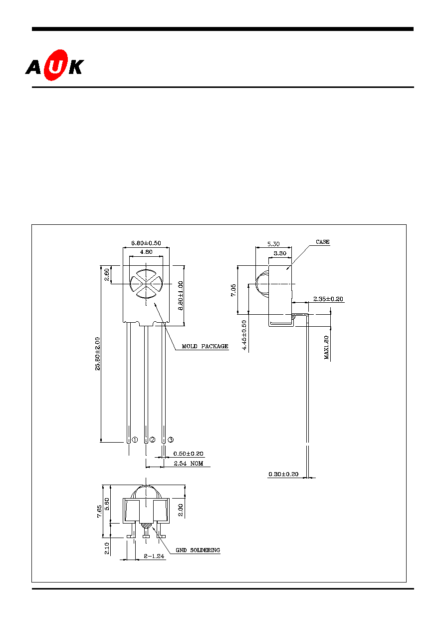
Outline Dimensions unit :
mm
S
S
e
e
m
m
i
i
c
c
o
o
n
n
d
d
u
u
c
c
t
t
o
o
r
r
PIN Connections
1.
Output
2.Gnd
3.Vcc(+5V)

KMM-1002-000
2
SRM-354VF
Absolute maximum ratings
Characteristic
Symbol
Ratings
Unit
Supply Voltage
V
CC
6.0
V
Power Dissipation
P
D
0.27
W
Operating Temperature
T
opr
-10 ~ 60
Storage Temperature
T
stg
-20 ~ 75
*
1
Soldering Temperature
T
sol
260 within 5 seconds
*1.Keep the distance more than 2.0mm from PCB to the bottom of package
Electrical Characteristics
(Ta=25
∞
C)
Parameter
Symbol
Test Condition
Min.
Typ.
Max.
Unit
Supply Voltage
V
cc
-
4.5
5.0
5.5
V
Current Consumption
I
CC
#1
0.3
-
1.5
mA
Resonance Frequency
f
C
-
-
38
-
KHz
Peak sensitivity wavelength
P
-
-
980
-
nm
H level output voltage
V
OH
4.5
5.0
-
V
L level output voltage
V
OL
-
0.2
0.4
V
H level pules width
T
wh
500
-
700
us
L level pules width
T
wl
#2
500
-
700
us
± 0∞
-
20
-
± 30∞
-
15
-
Arrival distance
L
#2,3,4
± 45∞
-
10
-
m
Output form
Active low

KMM-1002-000
3
SRM-354VF
Characteristic Diagrams
S(
)
-
R
e
la
tiv
e
S
p
ec
tr
a
l
S
e
n
s
it
iv
ity
Supply Voltage Vcc[V]
Input Current [A]
Fig. 3 System Gain - Frequency
Sy
s
t
e
m
G
a
i
n
[
d
B
]
Wavelength [nm]
drel-Relative Transmission Distance
Directivity tsop
Fig. 1 Relative Spectral Sensitivity - Wavelength
Fig. 2 drel-Relative Transmission Distance
Directivity tsop
Fig. 3 System Gain - Frequency
Frequency [Hz]
KMM-1002-000
4
SRM-354VF
# 1. No input signal.
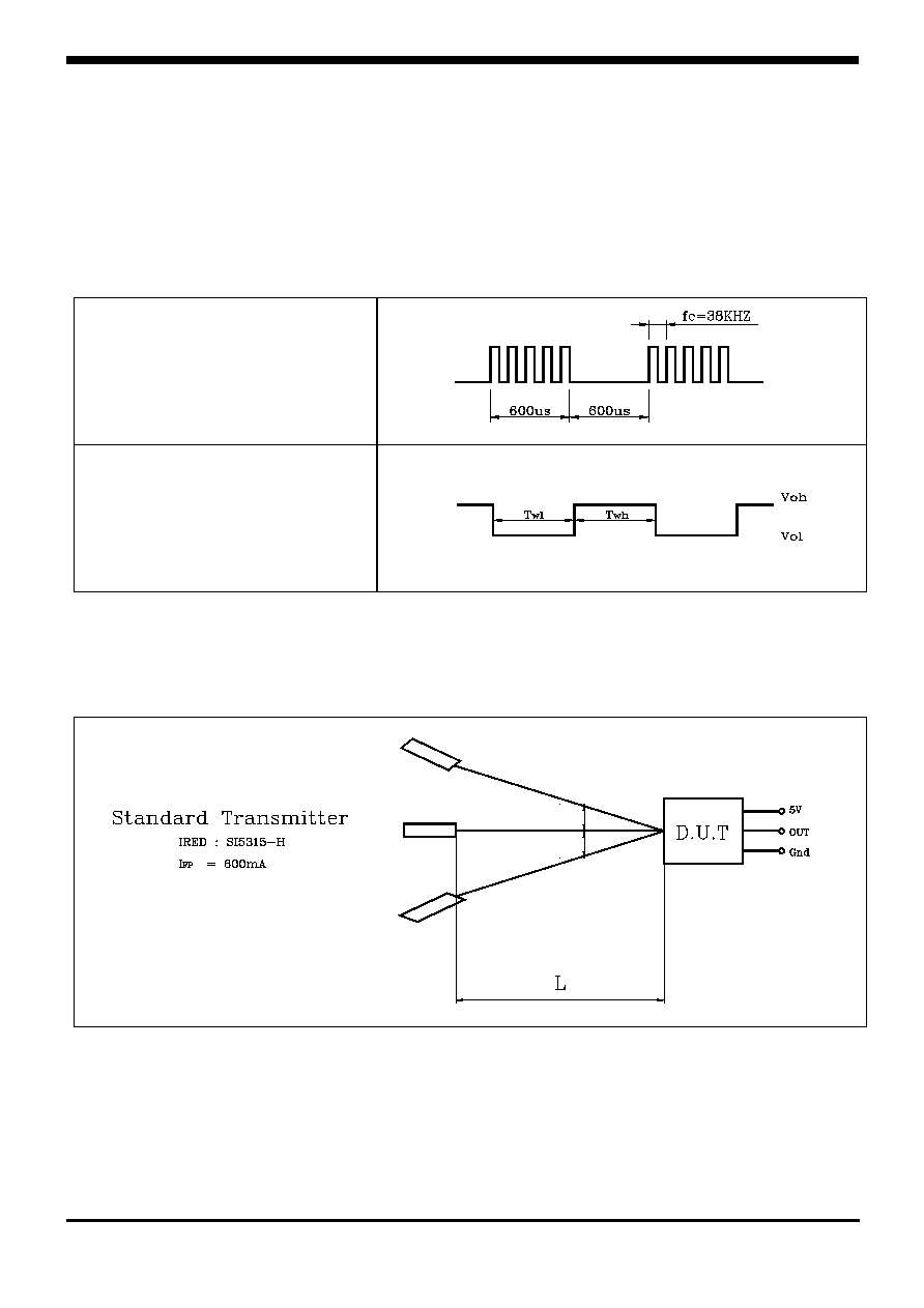
# 2. The burst wave forms shown below in the Fig 1. Shall be transmitted by the standard
transmitter.
Fig 1. Transmitter & Receiver wave forms
# 3. The test condition of arrival distance.
#4. The arrival distance is measured in the darkness without disturbing noises.
Transmitter Output Waveform
Receiver Module Output Waveform

KMM-1002-000
5
SRM-354VF
Reliability Test
Test items
Test condition
Remarks
High temp & High humid
Ta=40, RH=90%, t=96Hr's
#1, 2
Heat cycle
#2, 3
-
Fall test
#4
-
#1. Supply voltage 5V at the load test.
#2. Electro-optical characteristics shall be satisfied after 2hr's at normal temperature.
#3. Heat cycle test as below Fig2. For 20 cycles under no load.
Fig 2. Heat cycle test
#4. Fall test
The test devices to fall three time onto hard wooden board from a level 75
The others
In case of noisy power supply, please serially insert about 47 resistance an about 47
electrolytic capacitance in line as follows.
Remocon
Preamp