 | –≠–ª–µ–∫—Ç—Ä–æ–Ω–Ω—ã–π –∫–æ–º–ø–æ–Ω–µ–Ω—Ç: ATTINY12 | –°–∫–∞—á–∞—Ç—å:  PDF PDF  ZIP ZIP |

1
1006D≠AVR≠07/03
Features
∑
Utilizes the AVR
Æ
RISC Architecture
∑
High-performance and Low-power 8-bit RISC Architecture
≠ 90 Powerful Instructions ≠ Most Single Clock Cycle Execution
≠ 32 x 8 General Purpose Working Registers
≠ Up to 8 MIPS Throughput at 8 MHz
∑
Nonvolatile Program and Data Memory
≠ 1K Byte of Flash Program Memory
In-System Programmable (ATtiny12)
Endurance: 1,000 Write/Erase Cycles (ATtiny11/12)
≠ 64 Bytes of In-System Programmable EEPROM Data Memory for ATtiny12
Endurance: 100,000 Write/Erase Cycles
≠ Programming Lock for Flash Program and EEPROM Data Security
∑
Peripheral Features
≠ Interrupt and Wake-up on Pin Change
≠ One 8-bit Timer/Counter with Separate Prescaler
≠ On-chip Analog Comparator
≠ Programmable Watchdog Timer with On-chip Oscillator
∑
Special Microcontroller Features
≠ Low-power Idle and Power-down Modes
≠ External and Internal Interrupt Sources
≠ In-System Programmable via SPI Port (ATtiny12)
≠ Enhanced Power-on Reset Circuit (ATtiny12)
≠ Internal Calibrated RC Oscillator (ATtiny12)
∑
Specification
≠ Low-power, High-speed CMOS Process Technology
≠ Fully Static Operation
∑
Power Consumption at 4 MHz, 3V, 25∞C
≠ Active: 2.2 mA
≠ Idle Mode: 0.5 mA
≠ Power-down Mode: <1 µA
∑
Packages
≠ 8-pin PDIP and SOIC
∑
Operating Voltages
≠ 1.8 - 5.5V for ATtiny12V-1
≠ 2.7 - 5.5V for ATtiny11L-2 and ATtiny12L-4
≠ 4.0 - 5.5V for ATtiny11-6 and ATtiny12-8
∑
Speed Grades
≠ 0 - 1.2 MHz (ATtiny12V-1)
≠ 0 - 2 MHz (ATtiny11L-2)
≠ 0 - 4 MHz (ATtiny12L-4)
≠ 0 - 6 MHz (ATtiny11-6)
≠ 0 - 8 MHz (ATtiny12-8)
Pin Configuration
1
2
3
4
8
7
6
5
(RESET) PB5
(XTAL1) PB3
(XTAL2) PB4
GND
VCC
PB2 (T0)
PB1 (INT0/AIN1)
PB0 (AIN0)
ATtiny11
PDIP/SOIC
1
2
3
4
8
7
6
5
(RESET) PB5
(XTAL1) PB3
(XTAL2) PB4
GND
VCC
PB2 (SCK/T0)
PB1 (MISO/INT0/AIN1)
PB0 (MOSI/AIN0)
ATtiny12
PDIP/SOIC
8-bit
Microcontroller
with 1K Byte
Flash
ATtiny11
ATtiny12
Rev. 1006D≠AVR≠07/03
2
ATtiny11/12
1006D≠AVR≠07/03
Description
The ATtiny11/12 is a low-power CMOS 8-bit microcontroller based on the AVR RISC
architecture. By executing powerful instructions in a single clock cycle, the ATtiny11/12
achieves throughputs approaching 1 MIPS per MHz, allowing the system designer to
optimize power consumption versus processing speed.
The AVR core combines a rich instruction set with 32 general-purpose working regis-
ters. All the 32 registers are directly connected to the Arithmetic Logic Unit (ALU),
allowing two independent registers to be accessed in one single instruction executed in
one clock cycle. The resulting architecture is more code efficient while achieving
throughputs up to ten times faster than conventional CISC microcontrollers.
ATtiny11 Block Diagram
The ATtiny11 provides the following features: 1K bytes of Flash, up to five general-pur-
pose I/O lines, one input line, 32 general-purpose working registers, an 8-bit
timer/counter, internal and external interrupts, programmable Watchdog Timer with
internal oscillator, and two software-selectable power-saving modes. The Idle Mode
stops the CPU while allowing the timer/counters and interrupt system to continue func-
tioning. The Power-down Mode saves the register contents but freezes the oscillator,
disabling all other chip functions until the next interrupt or hardware reset. The wake-up
or interrupt on pin change features enable the ATtiny11 to be highly responsive to exter-
nal events, still featuring the lowest power consumption while in the power-down modes.
The device is manufactured using Atmel's high-density nonvolatile memory technology.
By combining an RISC 8-bit CPU with Flash on a monolithic chip, the Atmel ATtiny11 is
a powerful microcontroller that provides a highly-flexible and cost-effective solution to
many embedded control applications.
The ATtiny11 AVR is supported with a full suite of program and system development
tools including: macro assemblers, program debugger/simulators, in-circuit emulators,
and evaluation kits.
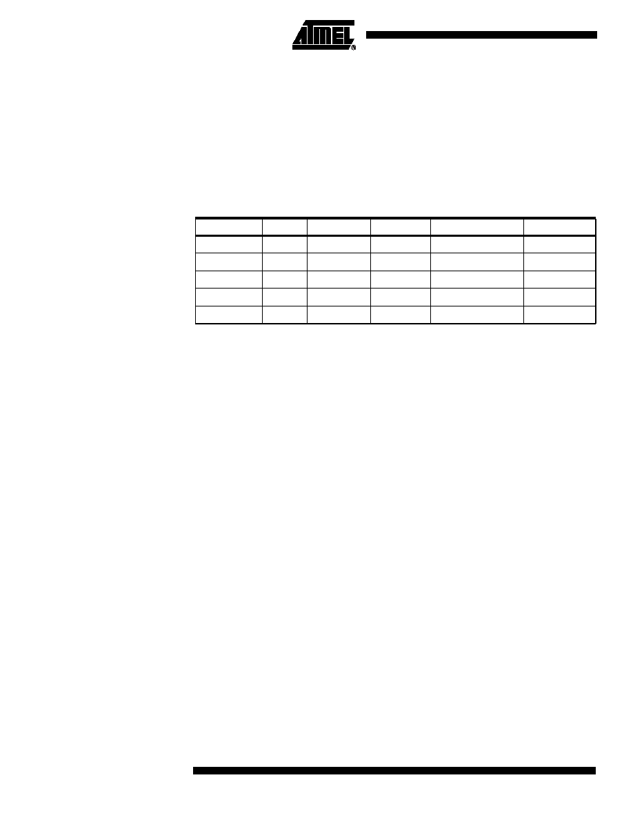
Table 1. Parts Description
Device
Flash
EEPROM
Register
Voltage Range
Frequency
ATtiny11L
1K
-
32
2.7 - 5.5V
0-2 MHz
ATtiny11
1K
-
32
4.0 - 5.5V
0-6 MHz
ATtiny12V
1K
64 B
32
1.8 - 5.5V
0-1.2 MHz
ATtiny12L
1K
64 B
32
2.7 - 5.5V
0-4 MHz
ATtiny12
1K
64 B
32
4.0 - 5.5V
0-8 MHz

3
ATtiny11/12
1006D≠AVR≠07/03
Figure 1. The ATtiny11 Block Diagram
PROGRAM
COUNTER
INTERNAL
OSCILLATOR
WATCHDOG
TIMER
STACK
POINTER
PROGRAM
FLASH
HARDWARE
STACK
MCU CONTROL
REGISTER
GENERAL-
PURPOSE
REGISTERS
INSTRUCTION
REGISTER
TIMER/
COUNTER
INSTRUCTION
DECODER
DATA DIR.
REG. PORTB
DATA REGISTER
PORTB
PROGRAMMING
LOGIC
OSCILLATORS
TIMING AND
CONTROL
INTERRUPT
UNIT
MCU STATUS
REGISTER
STATUS
REGISTER
ALU
PORTB DRIVERS
PB0-PB5
VCC
GND
CONTROL
LINES
+
-
ANALOG
COMP
ARA
T
O
R
8-BIT DATA BUS
Z
4
ATtiny11/12
1006D≠AVR≠07/03
ATtiny12 Block Diagram
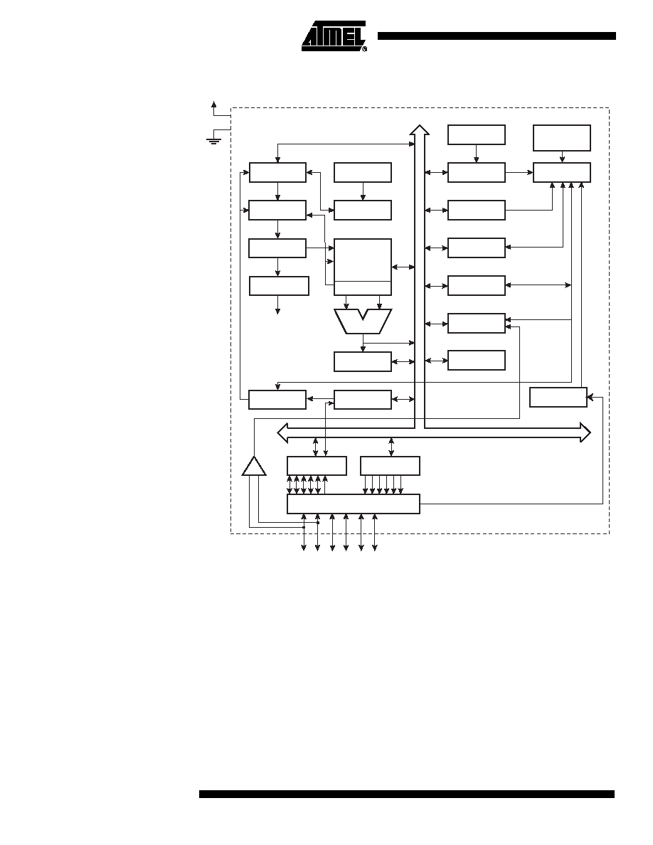
Figure 2. The ATtiny12 Block Diagram
The ATtiny12 provides the following features: 1K bytes of Flash, 64 bytes EEPROM, up
to six general-purpose I/O lines, 32 general-purpose working registers, an 8-bit
timer/counter, internal and external interrupts, programmable Watchdog Timer with
internal oscillator, and two software-selectable power-saving modes. The Idle Mode
stops the CPU while allowing the timer/counters and interrupt system to continue func-
tioning. The Power-down Mode saves the register contents but freezes the oscillator,
disabling all other chip functions until the next interrupt or hardware reset. The wake-up
or interrupt on pin change features enable the ATtiny12 to be highly responsive to exter-
nal events, still featuring the lowest power consumption while in the power-down modes.
The device is manufactured using Atmel's high-density nonvolatile memory technology.
By combining an RISC 8-bit CPU with Flash on a monolithic chip, the Atmel ATtiny12 is
a powerful microcontroller that provides a highly-flexible and cost-effective solution to
many embedded control applications.
PROGRAM
COUNTER
INTERNAL
OSCILLATOR
WATCHDOG
TIMER
STACK
POINTER
PROGRAM
FLASH
HARDWARE
STACK
MCU CONTROL
REGISTER
GENERAL-
PURPOSE
REGISTERS
INSTRUCTION
REGISTER
TIMER/
COUNTER
INSTRUCTION
DECODER
DATA DIR.
REG. PORTB
DATA REGISTER
PORTB
PROGRAMMING
LOGIC
OSCILLATORS
TIMING AND
CONTROL
INTERRUPT
UNIT
MCU STATUS
REGISTER
STATUS
REGISTER
ALU
PORTB DRIVERS
PB0-PB5
VCC
GND
CONTROL
LINES
+
-
ANALOG
COMP
ARA
T
O
R
Z
8-BIT DATA BUS
EEPROM
SPI
INTERNAL
OSCILLATOR
CALIBRATED

5
ATtiny11/12
1006D≠AVR≠07/03
The ATtiny12 AVR is supported with a full suite of program and system development
tools including: macro assemblers, program debugger/simulators, in-circuit emulators,
and evaluation kits.
Pin Descriptions
VCC
Supply voltage pin.
GND
Ground pin.
Port B (PB5..PB0)
Port B is a 6-bit I/O port. PB4..0 are I/O pins that can provide internal pull-ups (selected
for each bit). On ATtiny11, PB5 is input only. On ATtiny12, PB5 is input or open-drain
output. The port pins are tri-stated when a reset condition becomes active, even if the
clock is not running. The use of pins PB5..3 as input or I/O pins is limited, depending on
reset and clock settings, as shown below.
Notes:
1. "Used" means the pin is used for reset or clock purposes.
2. "-" means the pin function is unaffected by the option.
3. Input means the pin is a port input pin.
4. On ATtiny11, PB5 is input only. On ATtiny12, PB5 is input or open-drain output.
5. I/O means the pin is a port input/output pin.
XTAL1
Input to the inverting oscillator amplifier and input to the internal clock operating circuit.
XTAL2
Output from the inverting oscillator amplifier.
RESET
Reset input. An external reset is generated by a low level on the RESET pin. Reset
pulses longer than 50 ns will generate a reset, even if the clock is not running. Shorter
pulses are not guaranteed to generate a reset.
Clock Options
The device has the following clock source options, selectable by Flash fuse bits as
shown:
Table 2. PB5..PB3 Functionality vs. Device Clocking Options
Device Clocking Option
PB5
PB4
PB3
External Reset Enabled
Used
(1)
-
(2)
-
External Reset Disabled
Input
(3)
/I/O
(4)
-
-
External Crystal
-
Used
Used
External Low-frequency Crystal
-
Used
Used
External Ceramic Resonator
-
Used
Used
External RC Oscillator
-
I/O
(5)
Used
External Clock
-
I/O
Used
Internal RC Oscillator
-
I/O
I/O
Table 3. Device Clocking Options Select
Device Clocking Option
ATtiny11 CKSEL2..0
ATtiny12 CKSEL3..0
External Crystal/Ceramic Resonator
111
1111 - 1010
External Low-frequency Crystal
110
1001 - 1000
External RC Oscillator
101
0111 - 0101