
General Specifications
Surface Mount Terminations
25 Watts, 50
Model RFP-250375-4Z50-2
Resistive Element:
Thick film
Substrate:
Beryllium oxide ceramic
Terminals:
Thick film silver
Outline Drawing
.135
.058
.040
.135
.058
.060
.060
.250
.375
4Z50
250375
RFP
TOP VIEW
SIDE VIEW
BOTTOM VIEW
PROTECTIVE COATING
HATCHED AREA
INDICATES LOCATION OF
Notes: Tolerance is Ī.010, unless otherwise specified. Operating
temperature is -55įC to +125įC (see chart). Designed to meet or
exceed applicable portions of MIL-E-5400. All dimensions are in
inches.
Specifications subject to change without notice.
Electrical Specifications
Resistance Value:
50 ohms, Ī2%
Frequency Range:
DC - 2.0 GHz
Power:
25 Watts
V.S.W.R.:
1.25:1
Sur
face Mount T
e
r
minations
Features
∑ DC - 2.0 GHz
∑ 25 Watts
∑ BeO Ceramic
∑ Non-Nichrome Resistive
Element
∑ Low VSWR
∑ 100% Tested
1
Sales Desk USA: Voice: (800) 544-2414 Fax: (315) 432-9121
Sales Desk Europe: Voice: (+44) 23 92 232392 Fax: (+44) 23 92 251369
Available on Tape and Reel for Pick and Place Manufacturing.
VER. 12/5/01
Sur
face Mount T
e
r
minations
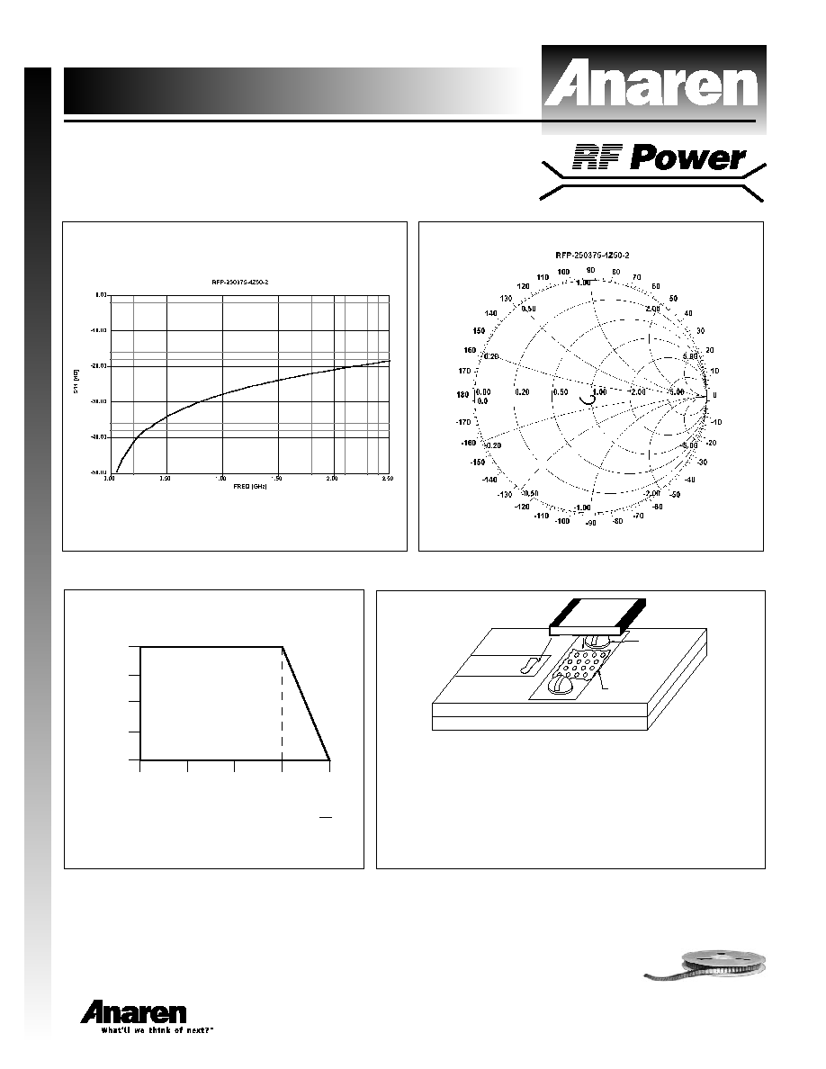
Model RFP-250375-4Z50-2
Typical Performance
2
Sales Desk USA: Voice: (800) 544-2414 Fax: (315) 432-9121
Sales Desk Europe: Voice: (+44) 23 92 232392 Fax: (+44) 23 92 251369
Power Derating
Suggested Mounting Procedures
125
100
75
50
100
75
50
25
0
25
% OF RATED POWER
P.C.B. SOLDER INTERFACE TEMPERATURE
įC
Available on Tape and Reel for Pick and Place Manufacturing.
(2 PLS.)
SCREW
SOLDER
PASTE
PC BOARD
HEATSINK
SOLDER
FILLED VIA
1. Solder part in place using 60/40 type solder with controlled
temperature iron (700įF).
2. Drill thermal vias through PCB and fill with solder, such as
60/40 type.
3. To ensure good thermal connectivity to heat sink, drill and
tap heatsink and mount PCB board to heat sink using
screws.