
T46L
TO-46 Lens
Package
T46F
TO-46 Ultra Flat
Window Package
AMT121302
1.25 Gb/s 1310/1550nm PIN TIA
Data Sheet - Rev 0
PRODUCT DESCRIPTION
The ANADIGICS AMT121302, packaged in a TO46
flat window or lens can, is a 5V integrated
photodetector and transimpedance amplifier (TIA)
used to convert a long wavelength (1270-1560nm)
input optical signal into a differential output voltage,
and is manufactured in ANADIGICS 6 GaAs wafer
fabrication facility. The TIA maximizes the
Figure 1: Block Diagram
receiver performance by providing a negative voltage
to reverse bias the photodetector which allows the
device to achieve high sensitivity and wide bandwidth.
These products are readily designed into receivers
and transceivers for Gigabit Ethernet and Fibre
Channel applications.
FEATURES
�
1.25 Gb/s Differential Output TIA
�
5.0V Operation
�
Automatic Gain Control
�
75 m 1270-1560nm InGaAs Photodetector
�
1000 MHz Minimum Bandwidth
�
-28dBm Typical Sensitivity
�
TO-46 Ultra Flat-Window or Lens Package
APPLICATIONS
�
Gigabit Ethernet (1.250 Gb/s)
�
Fibre channel (1.064 Gb/s)
m
4K
Charge
Pump
AGC
OUT
OUT
V
DD
4
2
1
3
6.5 GHz
OSC
US Patents: 5047728, 5646573
P
IN

2
AMT121302
Data Sheet - Revision 0
03/01
Table 1: Absolute Maximum Ratings
V
D
D
V
0
.
7
P
N
I
m
B
d
5
+
T
S
C
�
5
2
1
o
t
C
�
5
6
-
.
p
m
e
T
e
g
a
r
o
t
S
Table 2: Electrical Characteristics
Table 3: Package PIN Description
1.
Measured at -17 dBm optical input power with a SMF and output connected
into R
L
= 100 W (differential).
2.
Measured at 10
10
BER with a 2
7
-1 PRBS, 1.25 Gb/s.
3.
Input optical power = -3 dBm, R
L
= 100 W (differential).
4.
Measured with a 625 MHz, 50% duty cycle square wave.
5.
Measured with a 1.25 Gb/s, 2
7
-1 PRBS.
6.
1s about the center eye crossing.
7.
6s about the center eye crossing.
R
E
T
E
M
A
R
A
P
N
I
M
P
Y
T
X
A
M
T
I
N
U
)
(
h
t
g
n
e
l
e
v
a
W
0
7
2
1
0
6
5
1
m
n
r
e
t
e
m
a
i
D
r
o
t
c
e
t
e
D
5
7
m
�
y
ti
v
i
s
n
o
p
s
e
R
)
z
H
M
0
5
@
(
l
a
it
n
e
r
e
ff
i
D
l
a
n
g
i
S
ll
a
m
S
)
1
(
e
g
a
k
c
a
P
F
6
4
T
r
o
F
e
g
a
k
c
a
P
L
6
4
T
r
o
F
0
0
5
2
0
0
0
2
0
0
3
3
W
/
V
h
t
d
i
w
d
n
a
B
)
1
(
0
0
0
1
0
0
1
1
z
H
M
ff
o
t
u
C
y
c
n
e
u
q
e
r
F
w
o
L
0
0
8
z
H
k
e
c
n
a
t
s
i
s
e
R
t
u
p
t
u
O
5
2
0
4
0
6
e
g
a
tl
o
V
t
e
s
ff
O
t
u
p
t
u
O
2
.
2
V
d
a
o
lr
e
v
O
l
a
c
it
p
O
)
2
(
3
-
0
m
B
d
y
ti
v
it
i
s
n
e
S
l
a
c
it
p
O
)
2
(
e
g
a
k
c
a
P
F
6
4
T
r
o
F
e
g
a
k
c
a
P
L
6
4
T
r
o
F
6
2
-
5
2
-
8
2
-
m
B
d
e
g
a
tl
o
V
t
u
p
t
u
O
l
a
it
n
e
r
e
ff
i
D
)
4
(
,
)
3
(
0
5
3
0
0
6
V
m
T
E
S
I
R
T
&
L
L
A
F
)
%
0
8
-
0
2
(
)
4
(
,
)
3
(
0
6
1
0
6
2
s
p
n
o
it
r
o
t
s
i
D
e
l
c
y
C
y
t
u
D
)
5
(
,
)
3
(
3
6
%
r
e
tt
i
J
S
M
R
)
6
(
,
)
5
(
,
)
3
(
5
1
0
3
s
p
)
k
p
-
k
p
(
r
e
tt
i
J
l
a
t
o
T
)
7
(
,
)
5
(
,
)
3
(
0
9
0
5
1
s
p
t
n
e
r
r
u
C
y
l
p
p
u
S
5
3
0
5
A
m
e
g
n
a
R
e
g
a
tl
o
V
g
n
it
a
r
e
p
O
5
.
4
+
0
.
5
+
5
.
5
+
V
e
g
n
a
R
e
r
u
t
a
r
e
p
m
e
T
t
n
e
i
b
m
A
g
n
it
a
r
e
p
O
0
0
7
o
C
n
i
P
n
o
it
p
i
r
c
s
e
D
t
n
e
m
m
o
C
1
V
T
U
O
)
d
e
tr
e
v
n
I-
n
o
n
(
e
g
a
tl
o
V
t
u
p
t
u
O
A
I
T
-
t
u
p
n
i
l
a
c
it
p
o
h
ti
w
'
1
'
l
a
c
i
g
o
L
2
V
D
D
e
g
a
tl
o
V
y
l
p
p
u
S
e
v
it
i
s
o
P
-
s
tl
o
V
5
+
3
V
T
U
O
)
d
e
tr
e
v
n
I(
e
g
a
tl
o
V
t
u
p
t
u
O
A
I
T
-
t
u
p
n
i
l
a
c
it
p
o
h
ti
w
'
0
'
l
a
c
i
g
o
L
4
d
n
u
o
r
G
d
e
d
n
u
o
r
g
s
i
e
s
a
C
W
l

3
AMT121302
Data Sheet - Revision 0
03/01
Figure 2: Frequency Response *
Figure 3: Eye Diagram with an Optical Input Power of -3.0dBm
Figure 4: Eye Diagram with an Optical Input Power of -17dBm
0
5
10
15
20
25
30
35
0
500
1000
1500
2000
2500
3000
3500
Frequency (MHz)
Am
pl
i
t
ude (
d
B)
* Calibrated with an optical reference receiver with a gain of 21.62 dB at 50 MHz and a responsively
of 11.77462 A/W.
100mV/Div 200ps/Div
50mV/Div
200ps/Div

4
AMT121302
Data Sheet - Revision 0
03/01
Figure 5: Supply Current vs. Case Temperature
Figure 6: Bandwidth vs. Case Temperature
20
25
30
35
40
45
0
10
20
30
40
50
60
70
80
90
Case Temperature (C)
S
uppl
y
C
u
rrent
(m
A
)
4.5V
5.0V
5.5V
1040
1060
1080
1100
1120
1140
1160
0
10
20
30
40
50
60
70
80
90
Case Temperature (C)
B
andw
i
d
t
h
(M
H
z
)
4.5V
5.0V
5.5V
Figure 7: Differential Responsivity vs. Temperature
2500
2750
3000
3250
3500
3750
0
10
20
30
40
50
60
70
80
90
Case Temperature (C)
D
i
f
f
e
rent
i
a
l
R
e
s
pons
i
v
i
t
y
(V
/
W
)
4.5V
5.0V
5.5V
Figure 8: Sensitivity vs. Case Temperature
-28.80
-28.60
-28.40
-28.20
-28.00
-27.80
-27.60
-27.40
-27.20
-27.00
0
10
20
30
40
50
60
70
80
90
Case Temperature (C)
S
e
n
s
it
iv
it
y
(
d
B
m
)
4.5V
5.0V
5.5V

5
AMT121302
Data Sheet - Revision 0
03/01
Lightwave
Analyzer
HP 8702D
Laser
Optical Attenuator
DUT Test
Fixture
Power
Supply
Extinction
Ratio= 3dB
Figure 9: Test Setup for Frequency Response
Laser
Optical
Attenuator
DUT Test
Fixture
Power
Supply
Pulse Pattern
Generator
Limiting
Amplifier
Error
Detector
Hybrid
Coupler
Extinction
Ratio = 9dB
BERT
25 dB Gain
Figure 10: Test Setup for Sensitivity
Pulse Pattern
Generator
Laser
Optical
Attenuator
DUT Test
Fixture
Power
Supply
Digital
Communication
Analyzer HP83480A
Extinction
Ratio = 9dB
Figure 11: Test Setup for Eye Measurements

6
AMT121302
Data Sheet - Revision 0
03/01
V
OUT
V
OUT
DUT
0.1 uF
0.1uF
0.1uF
V
DD
Figure 12: DUT Test Fixture Schematic
Figure 13: Application Schematic
C
F
is an optional single pole noise filter
f
c
is the desired cutoff frequency
R
= 50 W
R
O
is required with high input resistance limiting amplifiers
R
O
= 100 W
f
c
R
C
F
=
2
1
4K
Charge
Pump
AGC
OUT
OUT
V
DD
4
2
1
3
LIMITING
AMPLIFIER
0.1uF
0.1uF
C
F
R
O
0.1uF
6.5 GHz
OSC

7
AMT121302
Data Sheet - Revision 0
03/01
4K
Charge
Pump
AGC
OUT
OUT
V
DD
4
2
1
3
0.1uF
0.1uF
0.1uF
V
OUT
V
OUT
6.5 GHz
OSC
Figure 14: Evaluation Board Schematic
Figure 15: Evaluation Board Layout
8
AMT121302
Data Sheet - Revision 0
03/01
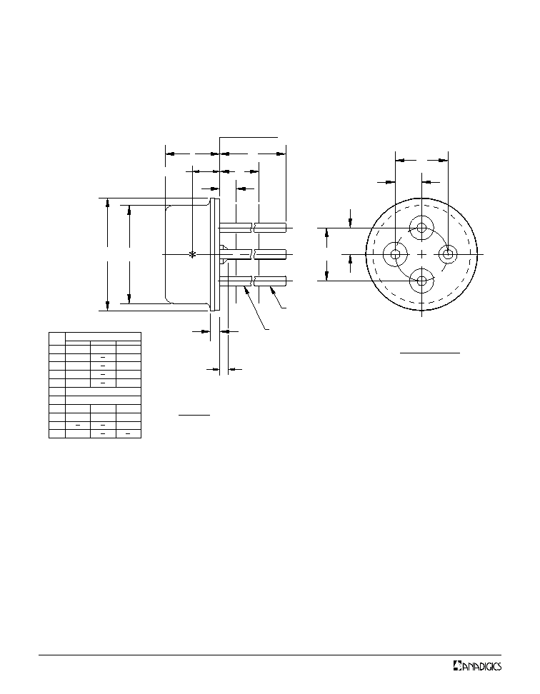
TO46-1300nm DIFFERENTIAL FLAT WINDOW
NOTES:
SEATING PLANE
�D1
�D
h
l
l
l
A
e
e
e
e
1
2
1
1
�b 2
�b
0.016 [0.41mm] MAX.
#4
#2
#1
#3
BOTTOM VIEW
1. INTERNAL OPTICAL HEIGHT = 0.065�0.005[1.65�0.1]
SEE NOTE 1
2. BENT LEADS SHOULD NOT EXTNED OUTSIDE
DIAMETER (�D) OF CAP OR TOUCH EACH OTHER.
3. ALL DIMENSIONS ARE REFENENCE ONLY-EXCEPT A, D & h.
12.70
6.35
0.30
4.60
MIN.
2.85
0.41
5.46
0.36
l
2
1
l
l
1
e
e
h
1
2
�b
�b
�D
�D
MB
Y
O
S
L
A
13.70
1.27
0.53
13.20
0.46
2.54 T.P.
1.27 T.P.
0.48
4.75
MAX.
3.00
0.51
5.61
2.95
NOM.
MILLIMETERS
Figure 16: T46F Package Outline Diagram

9
AMT121302
Data Sheet - Revision 0
03/01
Figure 17: T46L Package Outling Diagram

10
AMT121302
Data Sheet - Revision 0
03/01
Ordering Information
r
e
b
m
u
N
t
r
a
P
n
o
it
p
O
e
g
a
k
c
a
P
n
o
it
p
i
r
c
s
e
D
e
g
a
k
c
a
P
F
6
4
T
2
0
3
1
2
1
T
M
A
F
6
4
-
O
T
e
g
a
k
c
a
P
w
o
d
n
i
W
t
a
l
F
a
rt
l
U
L
6
4
T
2
0
3
1
2
1
T
M
A
L
6
4
-
O
T
e
g
a
k
c
a
P
s
n
e
L

11
AMT121302
Data Sheet - Revision 0
03/01
Notes

12
IMPORTANT NOTICE
ANADIGICS, Inc. reserves the right to make changes to its products or discontinue any product at any time without notice.
The Advanced Product data sheets and product specifications contained in this data sheet are subject to change prior to
a products formal introduction. The information in this data sheet has been carefully checked and is assumed to be reliable.
However, ANADIGICS assumes no responsibility for inaccuracies. ANADIGICS strongly urges customers to verify that the
information they are using is current before placing orders.
WARNING
ANADIGICS products are not intended for use in life support appliances, devices, or systems. Use of an ANADIGICS
product in any such application without written consent is prohibited.
ANADIGICS, Inc.
141 Mount Bethel Road
Warren, New Jersey 07059, U.S.A
Tel: +1 (908) 668-5000
Fax: +1 (908) 668-5132
http://www.anadigics.com
Mktg@anadigics.com
AMT121302