 | –≠–ª–µ–∫—Ç—Ä–æ–Ω–Ω—ã–π –∫–æ–º–ø–æ–Ω–µ–Ω—Ç: AP1551 | –°–∫–∞—á–∞—Ç—å:  PDF PDF  ZIP ZIP |

AP1551
150KHz, Dual Channel 2A PWM Buck DC/DC Converter
This datasheet contains new product information. Anachip Corp. reserves the rights to modify the product specification without notice. No liability is assumed as a result of the use of
this product. No rights under any patent accompany the sale of the product.
Rev. 1.0 Nov 17, 2004
1/8
Features
- Dual adjustable output channel
-
Adjustable output voltage range, 1.23V to
18V+4%
- 150KHz +15% fixed switching frequency
- Voltage mode non-synchronous PWM control
- Thermal-shutdown and current-limit protection
- ON/OFF shutdown control input
- Operating voltage can be up to 22V
- Output load current: 2A
- SOP-16L Pb-Free packages
- Low power standby mode
- Built-in switching transistor on chip
Applications
- Simple High-efficiency step-down regulator
- On-card switching regulators
- Positive to negative converter
General Description
The AP1551 is monolithic IC designed for dual
channel step-down DC/DC converters, and own the
ability of driving a 2A load each channel without
additional transistor component. Due to reducing
the number of external component, the board
space can be saved easily. The external shutdown
function can be controlled by logic level and then
come into standby mode. The internal
compensation makes feedback control have good
line and load regulation without external design.
Regarding protected function, thermal shutdown is
to prevent over temperature operating from damage,
and current limit is against over current operating of
the output switch. If current limit function occurred
and V
FB
is down to 0.5V below, the switching
frequency will be reduced. The AP1551 operates
at a switching frequency of 150KHz thus allowing
smaller sized filter components than what would be
needed with lower frequency switching regulators.
Other features include a guaranteed +4% tolerance
on output voltage under specified input voltage and
output load conditions, and +15% on the oscillator
frequency. The packages are available in a
standard 16-lead SOP-16 package.
Pin Assignments
1
2
3
15
14
13
12
11
10
9
8
7
6
5
4
16
( Top View )
SOP-16L
GND2
GND2
FB2
V
OUT2
FB1
V
OUT1
GND1
GND1
GND2
GND2
SD2
V
IN2
SD1
V
IN1
GND1
GND1
Pin Descriptions
Name
Description
V
IN1/2
Operating voltage input
V
OUT1/2
Switching
output
GND1/2
Ground
FB1/2 Output
voltage
feedback
control
SD1/2 ON/OFF
Shutdown

AP1551
150KHz, Dual Channel 2A PWM Buck DC/DC Converter
Anachip Corp.
www.anachip.com.tw
Rev. 1.0 Nov 17, 2004
2/8
Ordering Information
AP 1551 X X
Package
Packing
S: SOP-16L
Blank : Tube
A : Taping
Block Diagram
(Channel 1 and channel 2 are the same)
Current
Source
bias
1.235V
Reference
2.5V
Regulator
150kHz
OSC.
Start
up
+
+
_
+
_
Thermal
Shutdown
Pre-driver
Comp
Comp
GND
V
OUT1
V
IN1
SD1
FB1
220mV
200mV
2A
Switch
+
_
_
Amp
Comp
Frequecy
compen-
sation
AP1551
150KHz, Dual Channel 2A PWM Buck DC/DC Converter
Anachip Corp.
www.anachip.com.tw
Rev. 1.0 Nov 17, 2004
3/8
Absolute Maximum Ratings
Symbol
Parameter
Rating
Unit
V
CC
Supply
Voltage
+24
V
V
SD
ON/OFF Pin input voltage
-0.3 to +18
V
V
FB
Feedback Pin voltage
-0.3 to +18
V
V
OUT
Output voltage to Ground
-1
V
P
D
Power
dissipation
Internally limited
W
T
ST
Storage temperature
-65 to +150
o
C
T
OP
Operating temperature
-40 to +125
o
C
V
OP
Operating voltage
+4.5 to +22
V
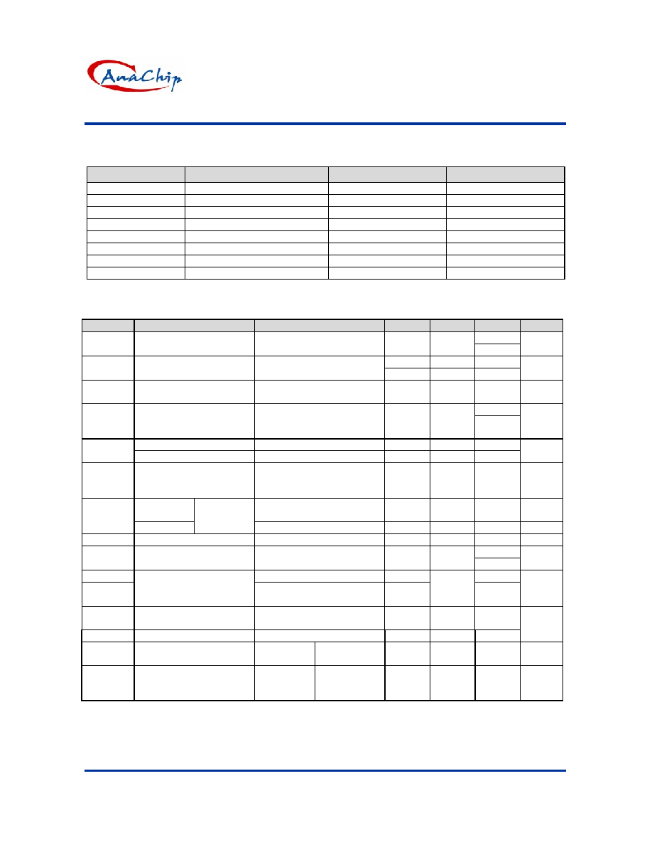
Electrical Characteristics
Unless otherwise specified, V
IN
=12V, I
LOAD
= 0.5A
Symbol
Parameter
Conditions
Min.
Typ.
Max.
Unit
-50
I
B1/2
Feedback bias current
V
FB1/2
=1.3V
(Adjustable version only)
- -10
-100
nA
127 150 173
F
OSC
Oscillator
frequency
110 - 173
KHz
F
SCP
Oscillator frequency of
short circuit protect
When current limit occurred
and V
FB1/2
< 0.5V, Ta=25
o
C
5 15 25
KHz
1.4
V
SAT1/2
Saturation
voltage
I
OUT1/2
=2A
No outside circuit
V
FB1/2
=0V force driver on
- 1.25
1.5
V
Max. Duty Cycle (ON)
V
FB1/2
=0V force driver on
-
100
-
DC
Min. Duty Cycle (OFF)
V
FB1/2
=12V force driver off
-
0
-
%
I
CL1/2
Current limit for each
channel
Peak current
No outside circuit
V
FB1/2
=0V force driver on
3 - - A
Output = 0
No outside circuit
V
FB1/2
=12V force driver off
- -
-200
uA
I
L1/2
Output = -1
Output
leakage
current
V
IN1/2
=22V -
-5
mA
I
Q1/2
Quiescent
Current
V
FB1/2
=12V force driver off
-
5
10
mA
150
I
STBY1/2
Standby Quiescent
Current
ON/OFF pin=5V
V
IN1/2
=22V
- 70
200
uA
V
IL1/2
Low (regulator ON)
-
0.6
V
IH1/2
ON/OFF pin logic input
threshold voltage
High (regulator OFF)
2.0
1.3
-
V
I
H
ON/OFF pin logic input
current
V
LOGIC
=2.5V (OFF)
-
-
-0.01
I
L
ON/OFF pin input current V
LOGIC
=0.5V (ON)
-
-0.1
-1
uA
JC
Thermal
Resistance SOP-16L
Junction to
case
- 15 -
o
C/W
JA
Thermal Resistance
With copper area of
approximately 3 in
2
SOP-16L
Junction to
ambient
- 70 -
o
C/W

AP1551
150KHz, Dual Channel 2A PWM Buck DC/DC Converter
Anachip Corp.
www.anachip.com.tw
Rev. 1.0 Nov 17, 2004
4/8
Electrical Characteristics (Continued)
Symbol
Parameter
Conditions
Typ.
Limit
Unit
V
FB1
Output
Feedback
4.5V < V
IN
< 22V
0.2A < I
LOAD
< 2A
V
OUT
programmed for
3V
1.23
1.193/1.18
1.267/1.28
V
V
MIN
V
MAX
AP1551-channel 1
Efficiency V
IN
= 12V, I
LOAD
=2A 76
%
V
FB2
Output
Feedback
4.5V < V
IN
< 22V
0.2A < I
LOAD
< 2A
V
OUT
programmed for
3V
1.23
1.193/1.18
1.267/1.28
V
VMIN
VMAX
AP1551-channel 2
Efficiency V
IN
= 12V, I
LOAD
=2A 76
%
Specifications with boldface type are for full operating temperature range, the other type are for T
J
=25∫C.
Typical Application Circuit
4 13
8 9
7 10
6 11
5 12
3 14
2 15
1 16
GND2
GND2
SD2
V
IN2
SD1
V
IN1
GND1
GND1
GND1
GND1
V
OUT1
FB1
V
OUT2
FB2
GND2
GND2
OFF ON
OFF ON
12V DC input
Cin
820uF
2.5V Vout1
3.3V Vout2
Cout1
470uF
Cout2
470uF
33uH
1.1k
1k
33uH
1.8k
1k
R1
R2
R3
R4
Vout1 =V
FB
◊
(1
+
R2
R1 );
Vout2 =V
FB
◊
(1
+
R4
R3 );
V
FB
= 1.235V
R2 = R4 = 1K ~ 3K

AP1551
150KHz, Dual Channel 2A PWM Buck DC/DC Converter
Anachip Corp.
www.anachip.com.tw
Rev. 1.0 Nov 17, 2004
5/8
Typical Performance Characteristics (For Each Channel)
AP1551 Efficiency v.s. Temperature
(Vin=12V,Vout=5V,Io=2A)
75
76
77
78
79
80
81
82
83
84
85
86
-50 -30 -10 10 30 50 70 90 110 130 150
Temperature (TA) (∞C)
E
ffi
c
i
e
n
c
y
(
%
)
AP1551 Efficiency v.s. Temperature
(Vin=12V,Vout=3.3V,Io=2A)
73
74
75
76
77
78
79
80
81
-50 -30 -10 10 30
50 70 90 110 130 150
Temperature (TA) (∞C)
Effi
ci
ency (%
)
AP1551 Saturation Voltage v.s. Temperature
(Vcc=12V,Vfb=0V,VSD=0)
0.7
0.8
0.9
1
1.1
1.2
1.3
1.4
-50
-25
0
25
50
75
100
125
Temperature (TA)(∞C)
S
a
turati
on V
o
l
t
age (V
)
2A
1A
0.5A
AP1551 Switch Current Limit v.s. Temperature
(Vcc=12V,Vfb=0V)
3
3.5
4
4.5
5
5.5
-50
-30
-10
10
30
50
70
90
Temperature (TA) (∞C)
Swi
t
ch Current
Li
mi
t
(A)
AP1551 Supply Current v.s. Temperature
(Vcc=12V , No Load ,Von/off =0V(Switch ON) ,Von/off =5V(Switch OFF))
5
6
7
8
9
10
11
12
13
14
15
-50 -30 -10 10
30
50
70
90 110 130 150
Temperature (TA) (∞C)
Supply
Current (m
A)
Switch ON
30
35
40
45
50
55
60
-50 -30 -10 10
30
50
70
90 110 130 150
Temperature (TA) (∞C)
Supply
Current (uA)
Switch OFF