
AH280
Hall-Effect Smart Fan Driver
This datasheet contains new product information. Analog Corp. reserves the rights to modify the product specification without notice. No liability is assumed as a result of the use of
this product. No rights under any patent accompany the sale of the product.
Rev. 0.7 Apr 16, 2004
1/7
Features
- On chip Hall plate
- Built-in Zener diode protection for output driver
- Built-in protection diode for power reverse
connecting
- Rotor-lock
detection
- Automatically restart after release of motor
locking
- Adjustable auto restart time
- Operating voltage: 3.5~20 V
- Max Output current: I
O(AVE)
= 500mA
- Packages: SIP-5L, SOP-8L, SOP-8L EP
- Less external component
Pin Assignments
Front View
( Branded side)
1
5
4
3
2
SIP-5L
3
4
8
7
6
5
2
1
DO
VCC
NC
DOB
GND
NC
NC
CT
( Top view )
SOP-8L / SOP-8L EP
General Description
AH280 is the integrated Hall sensor owned two
complementary outputs for motor's coil driving, auto
locked shutdown and auto restart functions.
Functional block diagram includes that a regulator
with temperature-compensated band-gap, an
on-chip Hall voltage generator, a comparator, a
Schmitt trigger and two current output drivers. The
regulator can provide wide operational voltage
range. The Hall voltage generator is to amplify the
Hall voltage due to Hall effect. A Schmitt trigger is
to provide switching Hysteresis for noise rejection.
To avoid coil burning, rotor-lock detection circuit will
shutdown the output driver if detect rotor-lock status.
A rotation recovery circuit is to restart the motor
after rotor-lock is removed. In addition, the auto
re-start time is flexible by adjusting the capacitance
(C
T
).
Pin Descriptions
SIP-5L
Symbol P/I/O Pin #
Description
CT I 1 Timing
cap.
VCC
P
2
Positive power supply
DO O 3 Driver
output
DOB
O
4
Driver inverted output
GND P 5 Ground
SOP-8L/SOP-8L EP
Symbol
Pin #
Description
VCC
1
Positive power supply
DO 2
Driver
output
DOB
3
Driver inverted output
NC
4,6,7
Not connected for SOP8
CT 8
Timing
cap.
GND 5
Ground

AH280
Hall-Effect Smart Fan Driver
Anachip Corp.
www.anachip.com.tw Rev. 0.7 Apr 16, 2004
2/7
Block Diagram
Hall
sensor
Control
Logic
Regulator
3
4
Lock Shutdown
Auto restart
circuits
5
1
Vcc
CT
Gnd
DOB
DO
2
Amp
Ordering Information
AH280 X - X X X - X
Packing
Blank : Tube or Bulk
A : Tape & Reel
P: SIP-5L
S: SOP-8L
SP: SOP-8L EP
Package
Lead
L : Lead Free
Blank: Normal
Wafer Body
Magnetic
Characteristics
Blank or
A~Z : if necessary
to specify
A or B
Application Circuit
Coil2
Coil1
( Top view )
AH280
D
Power
input
C
T
C
1
10�F
( DC Brush-less Fan )
AH280
Hall-Effect Smart Fan Driver
Anachip Corp.
www.anachip.com.tw Rev. 0.7 Apr 16, 2004
3/7
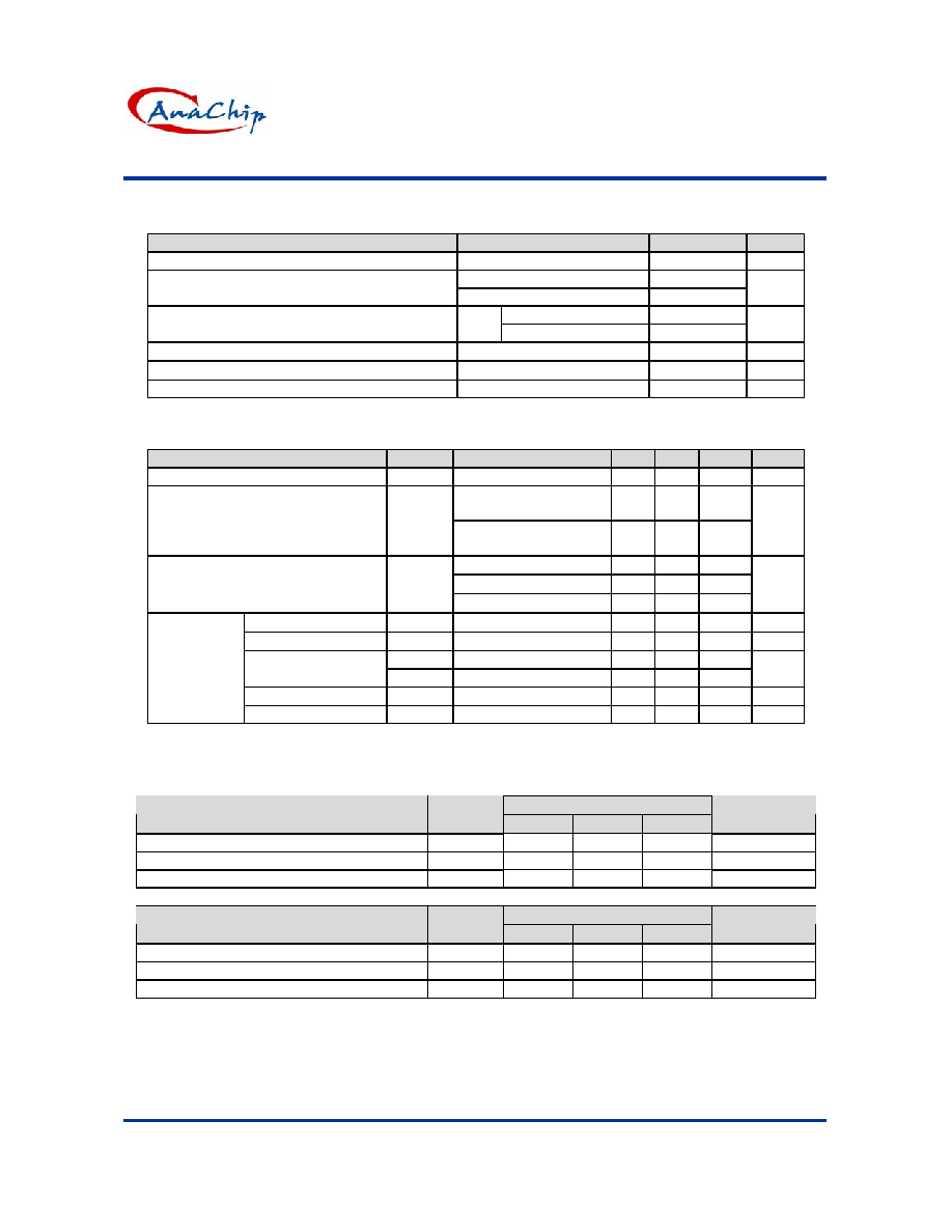
Absolute Maximum Ratings
(T
A
= 25
�C)
Characteristics
Symbol
Rating
Unit
Operating Supply Voltage
V
CC
20
V
I
O
(AVE)
500
Output Current
I
O (PEAK)
800
mA
SIP-5L / SOP-8L
550
Power Dissipation
P
D
SOP-8L EP
1000
mW
Operating Temperature
T
OPR
-20~85
�C
Storage Temperature
T
STG
-55~150
�C
DO(DOB) Vceo D.C. Voltage
Vceo
40
Vdc
Electrical Characteristics
(T
A
=25
�C, V
CC
=12V, C
T
=1�F)
Characteristics
Symbol
Test Conditions
Min, Typ. Max.
Unit
Internal Zener-protected Voltage
V
Z
- -
46
-
V
V
CC
=5V
Output1 "ON"
10 15 20
Quiescent current
I
Q
V
CC
=12V
Output1 "ON"
10 17 20
mA
I
O
=0.2A, T
J
=25
�C
- 0.4 -
I
O
=0.4A, T
J
=25
�C
- 0.6 -
Output saturation voltage
DO
DOB
I
O
=0.5A, T
J
=25
�C
- 0.7 -
V
Charge current
I
CHG
- -
2.4
-
�A
Discharge current
I
DHG
- -
0.5
-
�A
V
CL
Clamp
Voltage
- 2.0 -
Limiting voltage
V
CP
Comparator
Voltage
- 1.0 -
V
On time
T
ON
C
T
=.47�F
- 250 - ms
Automatic
self-rotation
recovery
circuit
Duty ratio
D
R
T
OFF
/ T
ON
3
5
7
-
Magnetic Characteristics
(1mT = 10 Gauss)
A grade
T
A
= -20
�C to +85�C
Characteristics
Symbol
Min.
Typ.
Max.
Unit
Operate Point
B
OP
10 - 60
G
Release Point
B
RP
-60 - -10
G
Hysteresis B
HYS
- 100 -
G
B grade
T
A
= -20
�C to +85�C
Characteristics
Symbol
Min.
Typ.
Max.
Unit
Operate Point
B
OP
10 - 80
G
Release Point
B
RP
-80 - -10
G
Hysteresis B
HYS
- 100 -
G

AH280
Hall-Effect Smart Fan Driver
Anachip Corp.
www.anachip.com.tw Rev. 0.7 Apr 16, 2004
4/7
Rotation detection
The automatic restart circuit detects a motor lock
condition and automatically turns off the output
current. When the lock condition is cleared, the IC
automatically restarts and allows the motor to run.
In the AH280, automatic restart is performed in the
following manner. A motor lock condition is
detected when the Hall signal stops switching.
The output is ON when CT pin is being charged,
and OFF when CT pin is being discharged.
OFF
ON
CT
clamp
voltage
CT
comparator
voltage
T
off*
T
on*
CT
Motor locked
Motor locked detected
Motor output
Hall input
Motor locked
cleared
Reverts to normal operation
Output ON time (T
on
) and OFF time (T
off
)
Determined by the CT pin capacitor
Where
T
on
=
CHG
I
)
CP
V
CL
(V
C
-
�
(sec)
T
off
=
DHG
I
)
CP
V
CL
(V
C
-
�
(sec)
C is the capacitance of the CT pin external capacitor
V
CL
is the CT pin clamp voltage
V
CP
is the CT pin comparator voltage
I
CHG
is the CT pin charge current
I
DHG
is the CT pin discharge current

AH280
Hall-Effect Smart Fan Driver
Anachip Corp.
www.anachip.com.tw
Rev. 0.7 Apr 16, 2004
5/7
Performance Characteristics (SIP-5L / SOP-8L)
Ta (
�C)
25
50
60
70
80
85
90
95
100
105
110
115
120
Pd
(mW)
550
413
358
303 248 220 193 165
138
110
83 55 28
Power Dissipation Curve
0
100
200
300
400
500
600
0
25
50
75
100
125
150
Ta ( C)
Pd (m W )
85
Performance Characteristics (SOP-8L EP)
Ta (
�C)
25
50
60
70
80
85
90
95
100
105
110
115
120
Pd
(mW)
1000
800
720
640 560 520 480 440
400
360
320 280 240
P o w e r D is s ip a t io n C u r v e
1 0 0
2 0 0
3 0 0
4 0 0
5 0 0
6 0 0
7 0 0
8 0 0
9 0 0
1 0 0 0
0
2 5
5 0
7 5
1 0 0
1 2 5
1 5 0
T a ( C )
P d ( m W )
8 5
Marking Information
(1) SIP-5L
(2) SOP-8L / SOP-8L EP
280
Part Number
Year:
( Front View )
"2" = 2002
"1" = 2001
X XX X X
Nth week: 01~52
ID Code
Blank: normal
L: Lead Free Package
AH280
Part Number
Year:
( Front View )
"2" = 2002
"1" = 2001
X XX X X
Nth week: 01~52
ID Code
Blank : normal
L : Lead Free Package