 | –≠–ª–µ–∫—Ç—Ä–æ–Ω–Ω—ã–π –∫–æ–º–ø–æ–Ω–µ–Ω—Ç: AS2578 | –°–∫–∞—á–∞—Ç—å:  PDF PDF  ZIP ZIP |
Data Sheet
Rev. 3
1
AS2578 /B
March 1997
TELEPHONE CONTROLLER WITH
13 MEMORIES AND 2-WIRE BUS
Key Features
u
Low operating voltage
u
Low current consumption, standby
0.1
µ
A
u
Oscillator using Xtal or ceramic resonator (3.58 MHz)
u
Serial interface to external EEPROM
u
Consistent, simple and usable procedures
u
The settings are programmed via the keyboard and
stored in EEPROM or set by pin options
Dialler:
u
Data protection with 20 digit FIFO
u
Sliding cursor protocol with comparison
u
Automatic pause generation
u
Temporary MF select via keyboard
u
30 digit LNR (Last Number Redial)
u
13 x 20 digit memory (RAM) on chip
Tone Ringer:
u
Ring frequency discrimination
u
3 tone melody with 4 different repetition rates
u
Volume of melodies can be set in 4 steps
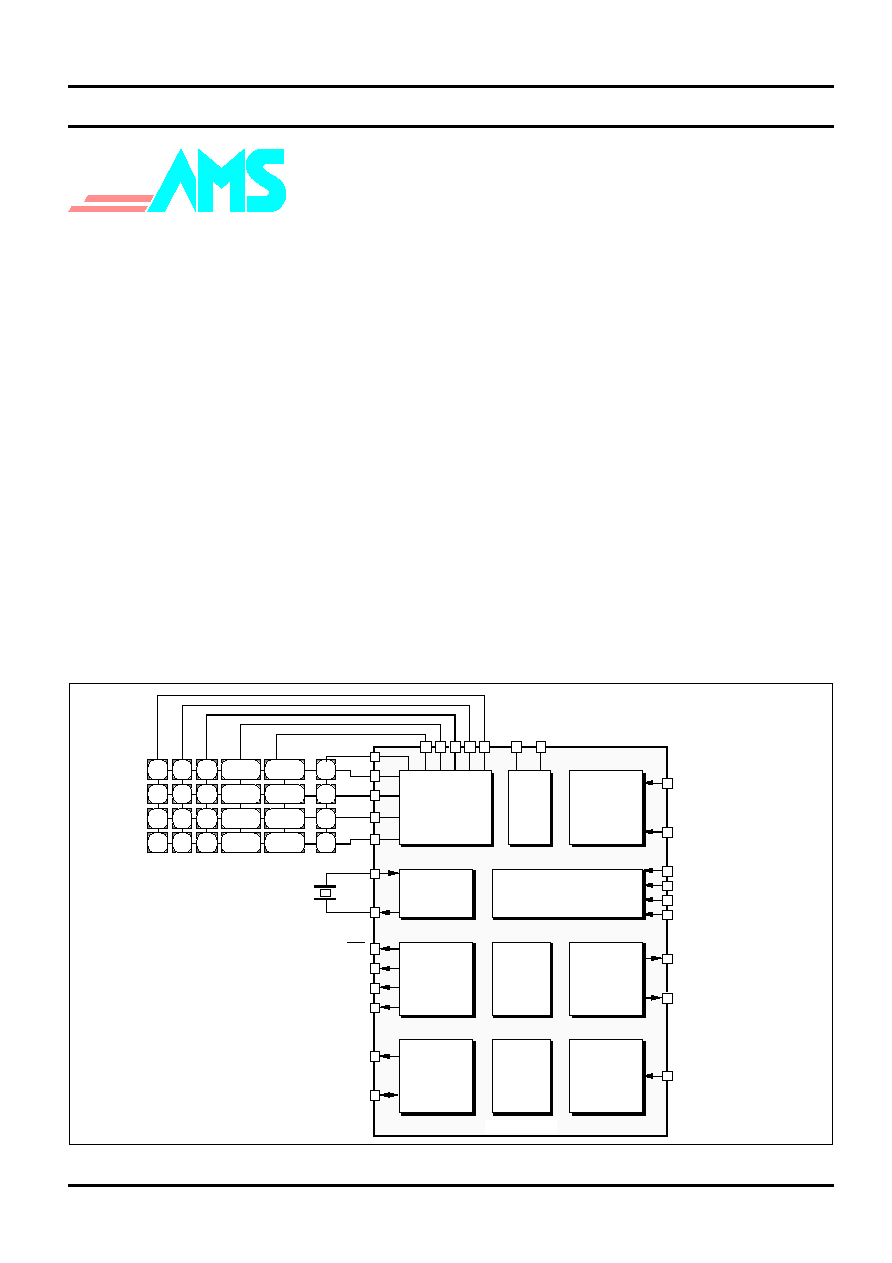
Block Diagramme
General Description
The AS2578 /B are a versatile repertory LD/MF diallers
with a melody generator, a ring frequency discriminator
and a 2-wire interface to EEPROM. Together with the
AS2520/1, the AS2578 /B form a coherent basis for a
fully electronic telephone with a wide range of options.
The AS2578 /B are especially designed to adapt to
different PTT specifications. A RAM is on chip for last
number redial, 3 direct dial and 10 numbers with
abbreviated dialling. To allow easy use under a PABX,
the device incorporates automatic pause insertion and
sliding cursor procedure as selectable options (AS2578)
or centrex keys (AS2578B). The device can be used with
or without EEPROM as appropriate. When an EEPROM
is connected, all RAM content is stored in the EEPROM
by power loss.
The circuit provides the possibility to set different modes
of operation (LM codes) via the keyboard or via pin
options, e.g. default signalling mode, automatic pause
insertion, flash or ground loop and settings of volume
and melodies.
Austria Mikro Systeme International
KEYSCAN
HOOK
STATE
CONTROL
DIAL
DTMF
MELODY
SERIAL
INTERFACE
RING
FREQUENCY
DETECTOR
POR
OSCILLATOR
REDIAL
13 X 20
1 X 30
RAM
FIFO
*
0
8
7
#
9
2
5
4
1
3
6
R
MUTE
SET
LNR
3.58 MHz
DP
GL
MUTE
SCL
SDA
FCI
MF
MO
MASK
HS
CE
MODE
AP (AS2578 only)
MV
RR
AS2578 /B
Vss V
DD
MEM
M1
M2
M3
D
C
B
A
(AS2578B)
Package
Available in 28 pin DIP and PLCC.
Æ
Data Sheet
Rev. 3
2
AS2578 /B
March 1997
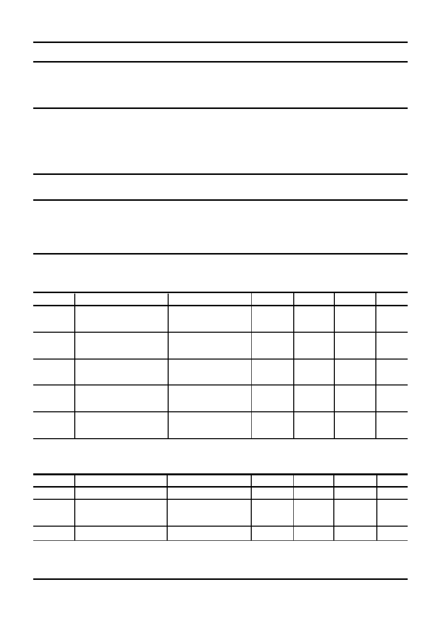
Pin Description
Pin #
Symbol
Function
1
C4
Keyboard Columns
2
C3
3
C2
4
C1
5
HS
Hook Switch Input
This input is active high with internal pull-down resistor.
6
MODE
Signalling (LD/MF) Default Mode Select Input
Mode pin
Function
High
LD default mode, make/break pulse 33/66 ms
Open
MF only
Low
LD default mode, make/break pulse 40/60 ms
7
CE
Chip Enable Input
This input is active high with internal pull-down resistor and is used to initiate setup
procedures.
8
OSC2
Oscillator Input
9
OSC1
Oscillator Output
Oscillator pins for Xtal or ceramic resonator (3.58 MHz). When a ceramic resonator is used
a capacitor (10 - 22 pF) must be connected from each of the oscillator pins to V
SS
.
10
Vss
Negative Power Supply
11
TONE
DTMF Tone Output
The dual tones provided at this output have a level independent of the supply voltage in
the operating range from 2.5 to 5.5V.
13
SDA
Serial Data I/O
SDA is a bidirectional pin with an open drain with internal pull-up resistor and is used to
transfer data into and out of a compatible EEPROM.
14
SCL
Serial Clock Line Output
The SCL output is an open drain with internal pull-up resistor and is used to clock data into
and out of a compatible EEPROM.
15
FCI
Frequency Comparator Input
Schmitt trigger input for ring frequency discrimination.
12
MO
Melody Generator Output
Melodies for tone ringing are generated on this output. The output signal is PDM.
16
MUTE
Mute Output
This push-pull output is high during dialling and when mute key has been activated,
otherwise low.
17
MASK
Mask Output
This push-pull output is high during pulsing (make and break periods).
Continues...
Data Sheet
Rev. 3
3
AS2578 /B
March 1997
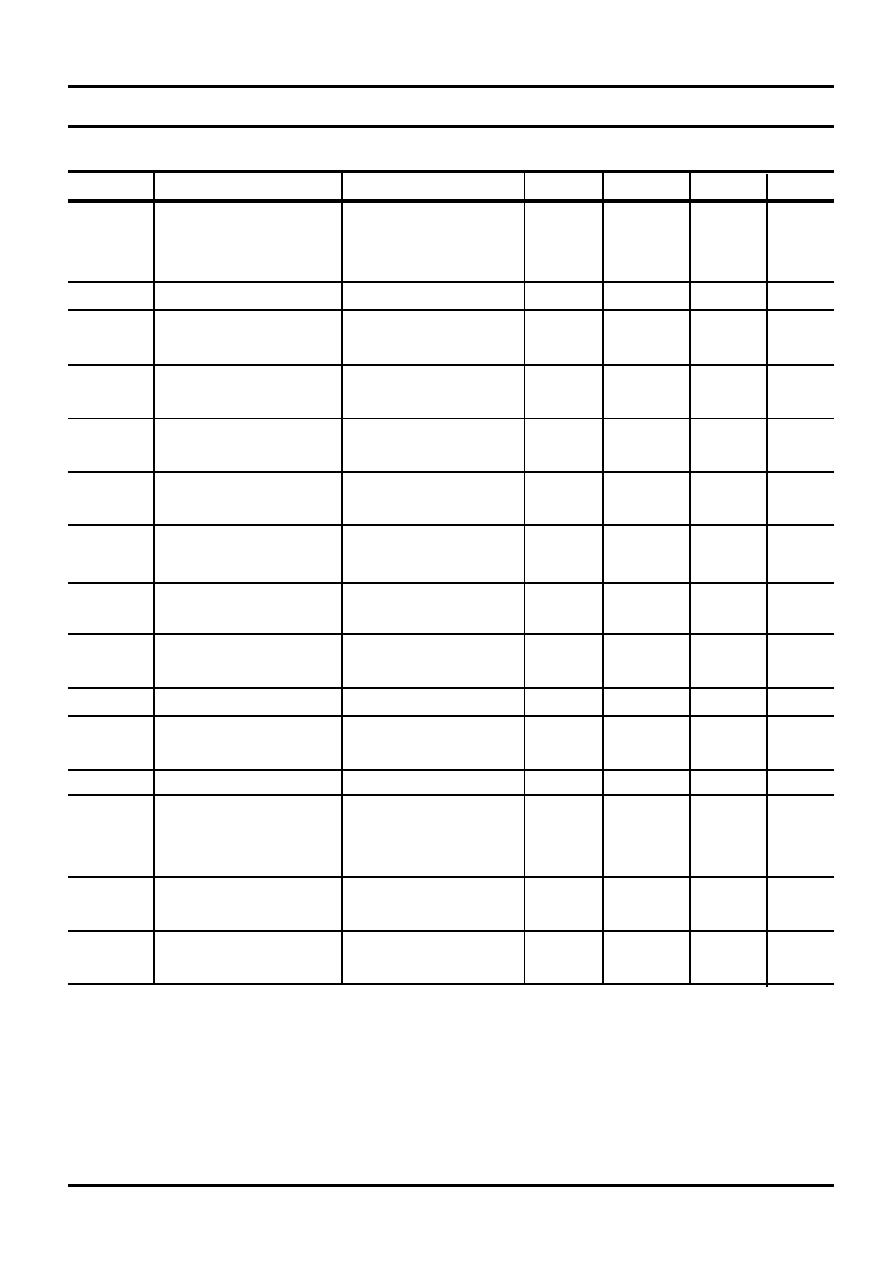
Pin Description cont¥d
Pin #
Symbol
Function
18
DPN
Dial Pulse Output
This is the push-pull output for controlling the hook-switch transistor. It is low during on-
hook and break periods and high during off-hook (see timing diagrammes).
19
GL
Ground Loop Output
This push-pull output is high during ground loop
20
V
DD
Positive Power Supply
21
R4
Keyboard Rows
22
R3
23
R2
24
R1
25
C5
Keyboard Column (AS2578)
This column is for the memory keys
C6
Keyboard Column (AS2578B)
This column is for centrex keys (A - D keys). Automatic pause insertion and Temporary
MF select 1 are fixed enabled (AP open)
26
AP
Access Pause Select Input (AS2578)
This input is used to select the automatic access pause insertion or sliding cursor (no
centrex keys):
AP pin
Function
High
Sliding cursor enabled
Temporary MF select 2
Open
Automatic pause insertion enabled
Temporary MF select 1
Low
Sliding cursor and pause disabled
Temporary MF select 1
C5
Keyboard Column (AS2578B)
This column is for the memory keys
27
MV
Melody Volume Select Input
This input is used to select the volume of the melodies in 4 steps by connecting the MV
pin to row 1, 2, or 3. Leaving the pin open is the default setting (max. volume).
28
RR
Repetition Rate Select Input
This input is used to select the repetition rate of the melodies. 4 different rates can be
selected by either leaving the pin open (default) or connecting it to column 1, 2, or 3.
Power On Reset
The on chip power on reset circuit monitors the supply
voltage (V
DD
). As long as V
DD
remains below the internal
reference voltage, Vref (typically 1.1V), the oscillator is
inhibited. When V
DD
rises above Vref (t
RISE
= 1
µ
s/V to 50
ms/V), a reset signal is generated to assure correct start-
up.
Initial Setup
A low to high transition on the CE input will initiate an
automatic setup, i.e. the pin options are scanned and
(when an EEPROM is connected) the stored LM codes
and melody settings are read from the EEPROM. This is
done independently of the hook state (see timing
diagrammes).
Note: "Open" means
100 k
.

Data Sheet
Rev. 3
4
AS2578 /B
March 1997
Memory Keys
The keys M1 to M3 are direct memory access keys and
the MEM key is used for abbreviated dialling.
13 numbers can be stored in on chip RAM. Each number
can contain up to 20 digits (including pauses).
If an EEPROM is connected to the serial bus, the content
of the RAM is written into the EEPROM when CE is
turned low indicating a power loss.
During programming multible pauses can be inserted by
pressing the LNR key.
Memory dialling is cascadable.
Mode Selection
The default mode (LD or MF) can be selected by the
MODE pin.
Furthermore, the mode can be selected by setting the
LM code (see setup menu). If no LM code is set, the
mode will be determined by the MODE pin.
When default LD mode is selected, a temporary change
to MF mode can be invoked by pressing * (AP = high,
AS2578 only) or Set, * , Set.
When the circuit is in temporary MF mode, each of the
following procedures revert it to default LD mode:
- pressing Set, * , Set ,
- pressing recall key (by further entries of the recall key
the signalling mode will toggle between MF and LD,
- by next On-hook.
Recall Function
A recall activation will invoke a flash (timed loop break)
or a ground loop (GL) depending on the selected LM
code, which is stored in the external EEPROM (see
setup menu).
If no LM code is set, depressing the recall key will invoke
both a flash and a GL, however, in LD mode a Flash is
never executed.
If recall is the first entry in a digit string, it will be stored
in LNR RAM when digit(s) are entered after the recall.
If the recall key is depressed after a digit string has been
entered or dialled out, the recall will not be stored, and
subsequently entered digits will be stored in the LNR
RAM as the new number.
If pressing the recall key is not followed by digit entries,
the LNR RAM remains intact.
Last Number Redial
LNR is a facility that allows resignalling of the last
manually dialled number without keying in all the digits
again. The LNR is repeatable.
The current contents of the RAM are overwritten by new
entries.
A manually entered number is automatically stored in the
LNR RAM. The capacity of the RAM is 30 digits. If a
number greater than 30 digits is entered, the LNR facility
will be inhibited (until new entries < 31 digits) and further
entries will be buffered in FIFO.
Postdialled digits, i.e. digits manually entered after LNR
has been invoked, are not stored in RAM but buffered in
FIFO.
Valid Keys
The keyscanning is enabled when CE or HS are high.
During setup the keyboard is disabled. A valid key is
detected from the keyboard by connecting the appropriate
row to the column. This can be done using an n x m
keyboard matrix with single contacts. Positive and
negative edges of each contact are debounced. The
debounce time is 15 ms.
Mute Key
The mute key is only enabled when off-hook. Depressing
the mute key activates and deactivates (toggle switch)
the MUTE output, when internal mute is inactive, i.e. in
speech mode.
Any key entry overwrites a mute activated by the mute
key, and mute will be deactivated.
Centrex Keys (AS2578B only)
The alphameric keys accommodate easy use of centrex
services. The A, B, C and D keys are only valid in MF
mode and are not storable. Pressing one of these keys
will invoke the appropriate MF tones to be transmitted.
The centrex keys are not stored in the RAM, but are
buffered in the FIFO, and subsequently entered digits
are also buffered in the FIFO.
Pressing the recall key after a sequence including centrex
keys will reset the RAM counter, and subsequently
entered digits will be stored in the RAM. If MF select (Set,
* , Set) has been invoked once, then all susequently
digits/data will be buffered in the FIFO.

Data Sheet
Rev. 3
5
AS2578 /B
March 1997
After a recall a pause will automatically be generated.
The pause time is 3 sec.
The ground loop (GL) has two pulse lengths, namely a
short of 500 ms and a long of 1250 ms.
Short GL: If the recall key is depressed for
540 ms, the
GL pulse is 500 ms.
Long GL: If the recall key is depressed for > 540 ms, the
GL pulse is 1250 ms.
During redial a ground loop is only executed as a long GL
(1250 ms).
Pause Generation
Pause introduces a delay in signalling digit strings to
accommodate second and subsequent dial tones.
Automatic pauses are generated in the following manner:
- always after a recall independent of the AP pin
- with automatic pause insertion enabled by pin option
or LM code, up to two pauses can be automatically
inserted at any location of the original entry in the RAM
(except location 1 of the digit string), when the mute
output goes inactive (in MF mode for more than 1 sec.)
before next entry.
A pause read from the RAM can be terminated (shortened)
prior to time out by a low level on AP pin (AS2578 only)
during the pause execution. The pause time is 3 sec.
During execution of a pause, mute is inactive, i.e. the
circuit is in speech mode.
Sliding Cursor Procedure (AS2578 only)
To accommodate redialling (LNR) behind a PABX without
using automatic pause generation, a sliding cursor
protocol is implemented. The sliding cursor is enabled
when AP = high. If new entries match the previous RAM
contents, pressing the LNR key will dial out the remaining
digits.
If there is an error in matching, the LNR will be inhibited
until next on-hook, and the RAM will contain the new
number.
Serial Interface
The AS2578 /B support a bidirectional bus oriented
protocol. The protocol defines any device that sends
data onto the bus as a transmitter, and the receiving
device as the receiver. The AS2578 /B are controlling the
transfer and hence the master. The EEPROM being
controlled is the slave.
The AS2578 /B will always initiate data transfer, and
provide the clock for both transmit and receive operations.
Therefore, the protocol is for single master applications
only.
However, a temporary second master can be used to
write into the EEPROM when the AS2578 /B are supplied
and in idle state.
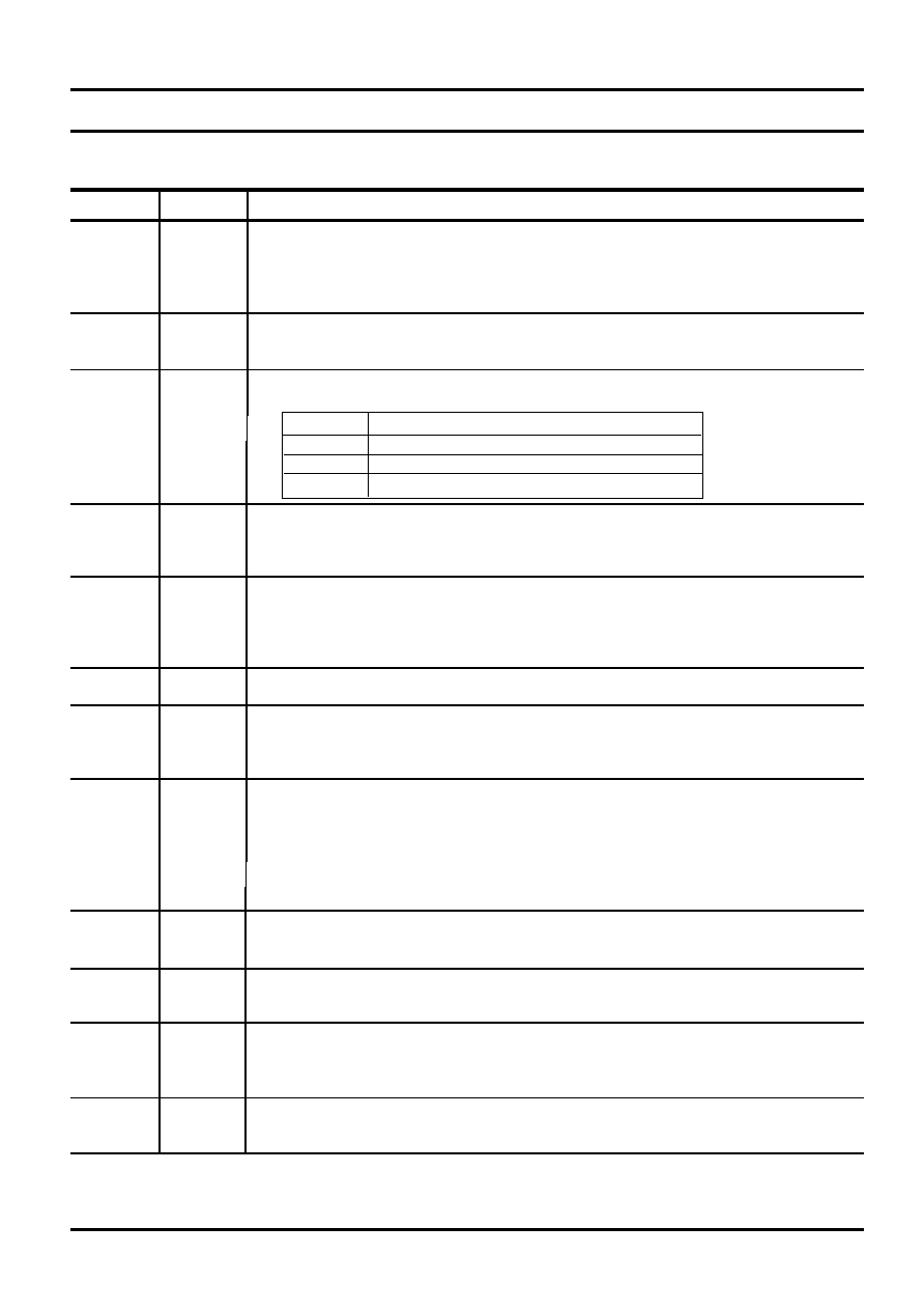
Clock and Data Conventions
Data states on the SDA line can change only during SCL
low. SDA state changes during SCL high are reserved
for indicating start and stop conditions (see figure 1 and
2).
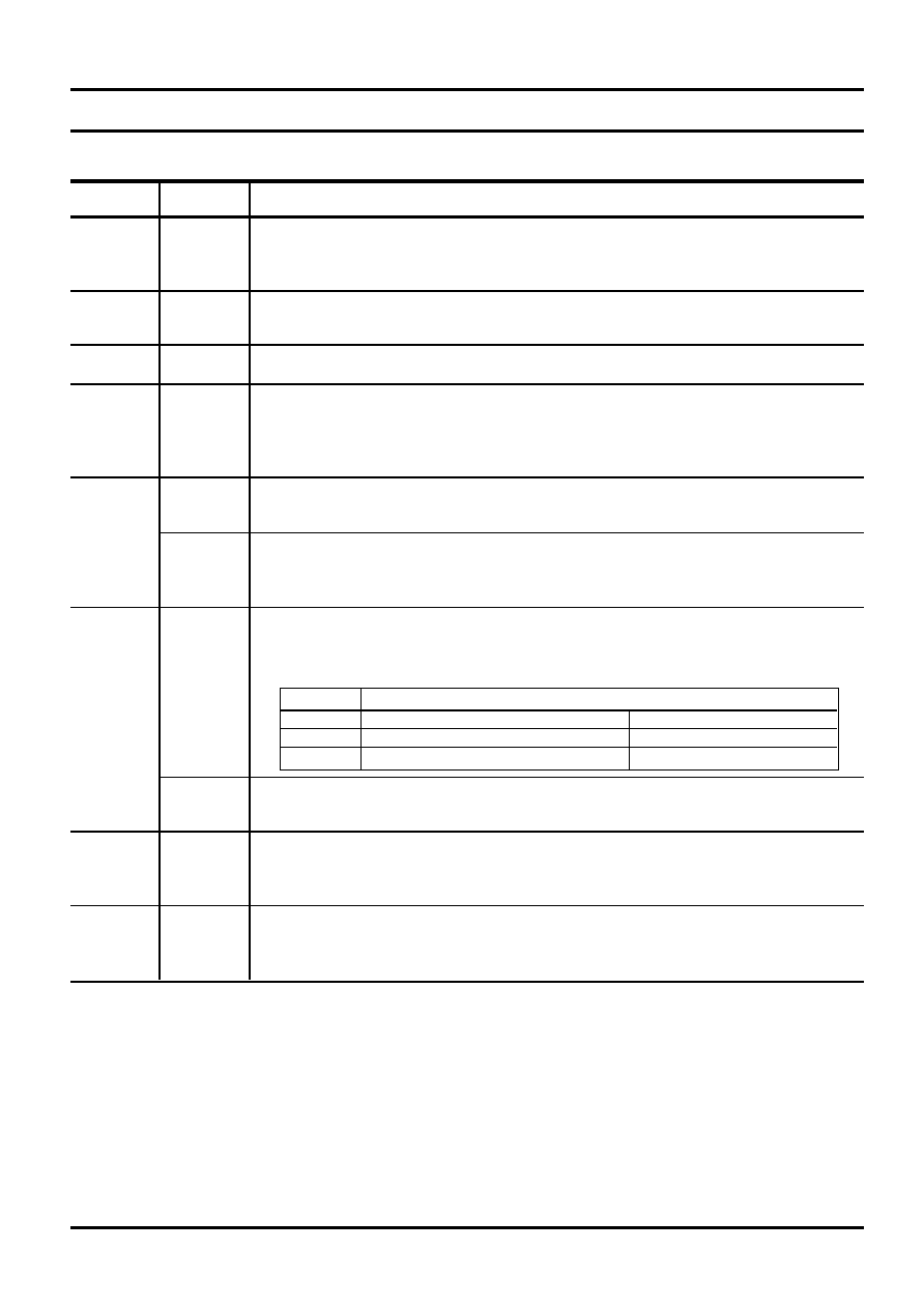
Start Condition
All commands are preceded by the start condition, which
is a high to low transition of SDA when SCL is high. The
slave should continuously monitor the SDA and SCL
lines for the start condition and must not respond to any
command until this condition has been met.
Stop Condition
All communications are terminated by a stop condition,
which is low to high transition of SDA when SCL is high.
The stop condition is also used to place the slave in the
standby power mode.
Acknowledge
Acknowledge is a software convention used to indicate
successful data transfers. The transmitting device, either
master or slave, will release the bus after transmitting
eight bits. During the ninth clock cycle the receiver will
pull the SDA line low to acknowledge that it received the
eight bits of data (see figure 3).
The slave should always respond with an acknowledge
after recognition of a start condition and its slave address.
If both the device and a write operation have been
selected, the slave should respond with an acknowledge
after receipt of each subsequent eight bit word.
In the read mode, when the EEPROM has transmitted
eight bits of data, it should release the SDA line and
monitor the line for an acknowledge. If the AS2578 /B
respond with an acknowledge and does not generate a
stop condition, the EEPROM should continue to transmit
data. If the AS2578 /B do not respond with an
acknowledge, the EEPROM should terminate further
Data Sheet
Rev. 3
6
AS2578 /B
March 1997
data transmission and await the stop condition to return
to the standby power mode.
data
change
data
stable
SDA
SCL
Figure 1 Data Validity
start
bit
stop
bit
SDA
SCL
Figure 2 Definition of Start and Stop
SCL from
master
Data out
from Tx
Data out
from Rx
1
8
9
start
acknowledge
Figure 3 Acknowledge Response From Receiver
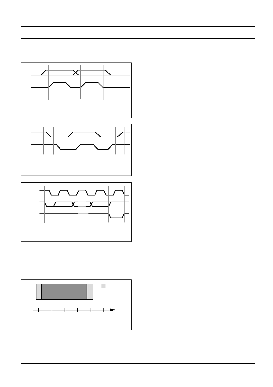
Frequency Comparator
The frequency comparator monitors that the ring signal
is in the limits as shown in figure 4.
Tone Generator
The tone generator incorporates the DTMF tones and 3
basic frequencies for the tone ringer.
DTMF
The DTMF generator provides 8 frequencies, namely:
Low group
Row 1
697 Hz
Row 2
770 Hz
Row 3
852 Hz
Row 4
941 Hz
High group
Col. 1
1209 Hz
Col. 2
1336 Hz
Col. 3
1477 Hz
Col. 6
1633 Hz
(AS2578B only)
The MF tones are in accordance with CEPT
recommendations.
Tone Ringer (Melody)
The three basic frequencies of the melodies are:
F1 = 800 Hz, F2 = 1067 Hz, and F3 = 1333 Hz (
±
5%).
The repetition rate can be set via key procedures or by
pin options as follows:
LM code
Repetition rate
1
1 time
(50 ms pause)
2 (default)
4 times
3
7 times
4
10 times
Repetition rate means that a sequence of 6 frequencies
is repeated 1 to 10 times within 1 sec. For LM code 1 a
pause of 50 ms is inserted between the frequencies to
allow a better recognition of the melodies.
The sequence of the frequencies is controlled by the
sequence register as follows:
Sequence
F1 F2 F3 F1 F2 F3 ...
The volume of the melodies (MO output) can be set as
follows:
LM code
Volume
Steps
1
- 17.5 dB
2
- 11.5 dB
6 dB
3
- 5.5 dB
6 dB
4
(default)
0 dB
5.5 dB
When a continious valid ring signal is present for 80 ms,
the melody generator is activated and remains active
until two or more periods of the ring signal are missing.
Ring
frequency
20
30
40
50
60
(Hz)
MUST
DETECT
Tol.
70
Figure 4 Detection Window of Ringing Signal
Data Sheet
Rev. 3
7
AS2578 /B
March 1997
LM Codes and Pin Options
LM code
Pin option
Function
02-2*
AP = L
Automatic pause insertion: off
Sliding cursor: off
MF select 1
02-3
AP = Hi-Z
Automatic pause insertion: on
Sliding cursor: off
MF select 1
-
AP = H
Automatic pause insertion: off
Sliding cursor: on
MF select 2
033*
MODE = L
LD mode 40/60
GL
033*
MODE = H
LD mode 33/66
GL
036
-
MF mode
GL
037
-
MF mode
Flash
-
MODE = Hi-Z
MF mode
GL + Flash
250
-
Resets all user settings to default and clears all RAM contents
258
-
Clears all RAM contents
5 - 4*
MV = Hi-Z
Melody volume:
0 dB
5 - 3
MV = R3
Melody volume:
- 5.5 dB
5 - 2
MV = R2
Melody volume:
- 11.5 dB
5 -1
MV = R1
Melody volume:
- 17.5 dB
6 - 1
RR = Hi-Z
Repetition rate:
1 time
(50 ms pause)
6 - 2*
RR = C1
Repetition rate:
4 times
6 - 3
RR = C2
Repetition rate:
7 times
6 - 4
RR = C3
Repetition rate:
10 times
Note 1: Programming an LM code overwrites pin options, however, LM code 033 can only be selected when the MODE
pin is connected to either high or low for selecting the make/break ratio. Not valid LM codes are ignored. LM
codes with a '*' are default settings.
Note 2: When the AP pin is pulled low during execution of a pause, the pause will be terminated.
Note 3: AP pin option not available on AS2578B.
Data Sheet
Rev. 3
8
AS2578 /B
March 1997
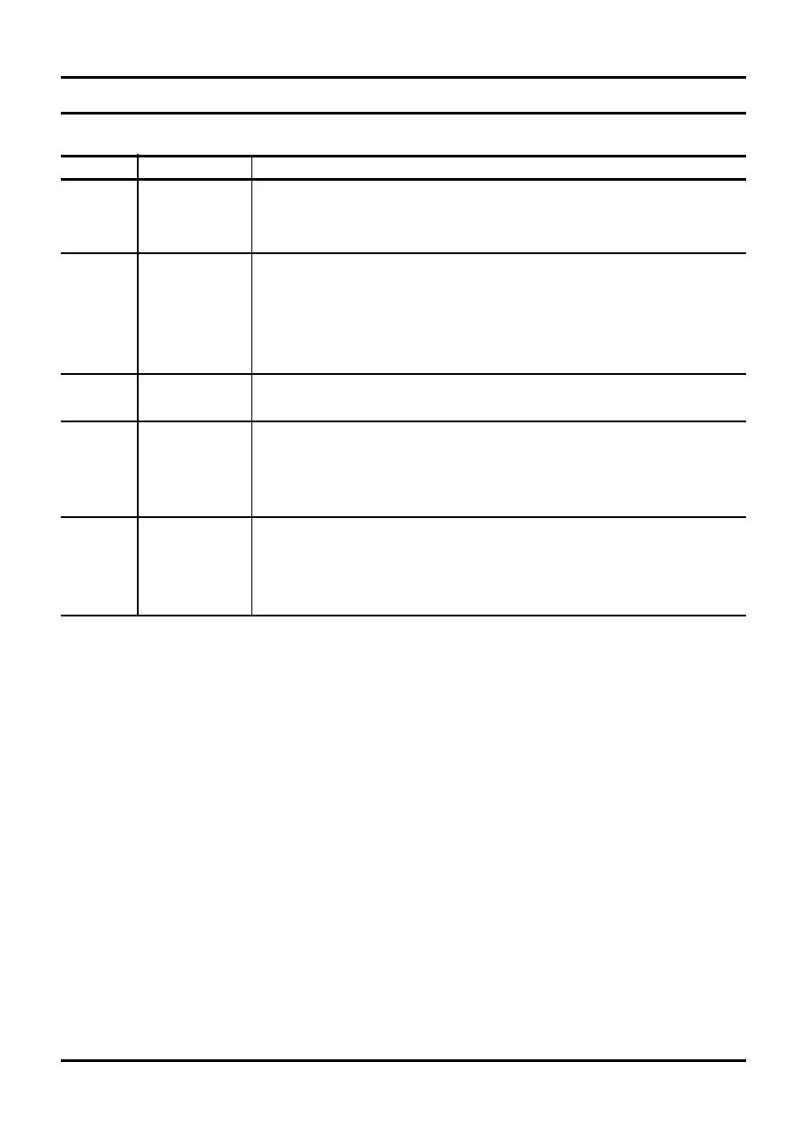
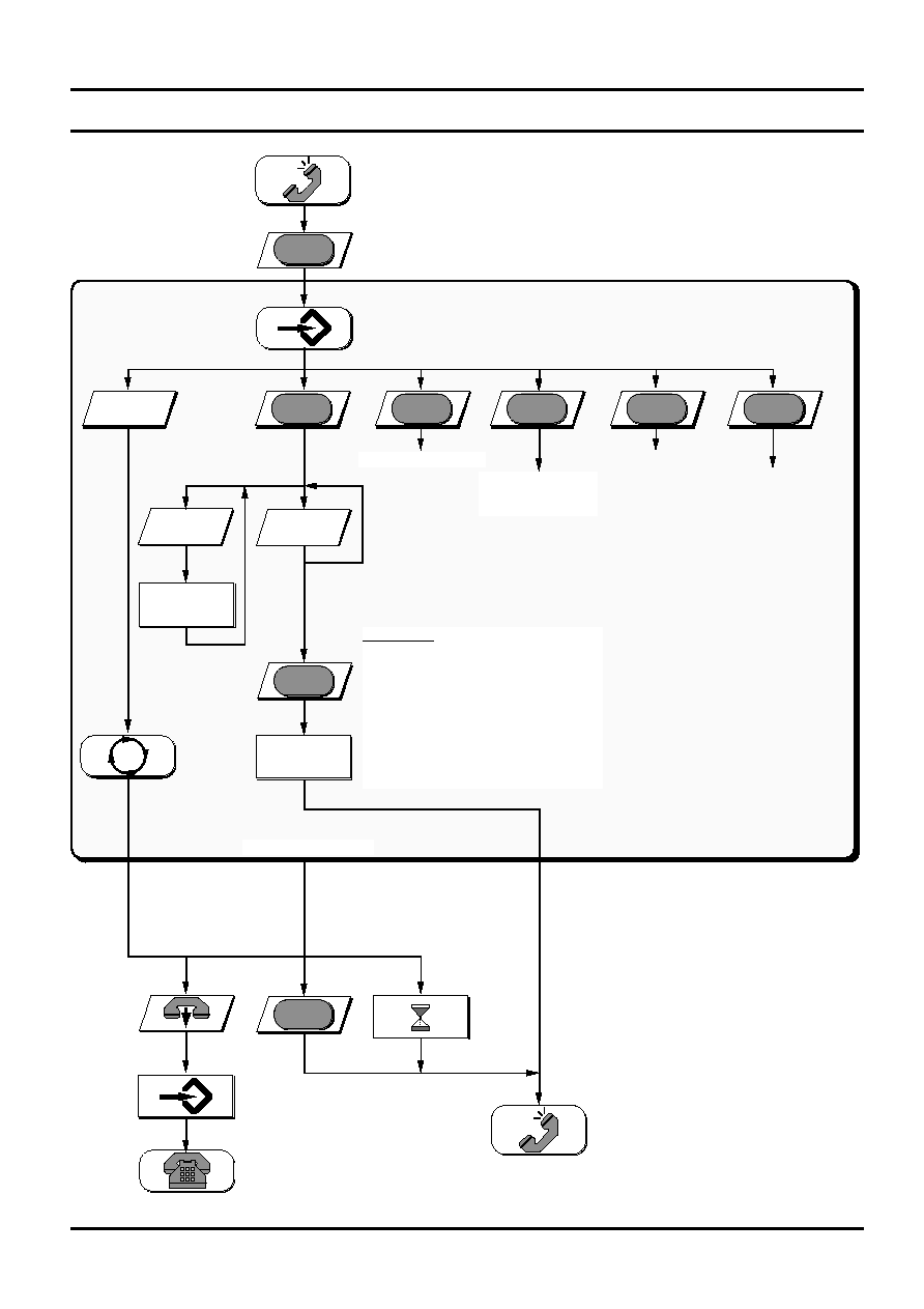
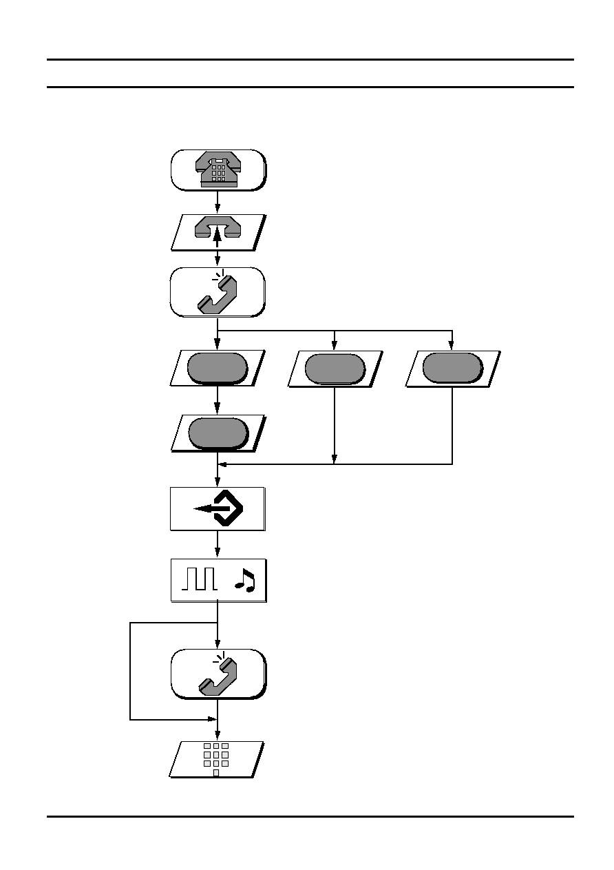
Operating Procedures
Procedure Principles
The procedures for utilizing the features of the AS2578 /B are optimized out of consideration for the human factor in
order to:
- meet the user¥s expectations
- be easy to learn and relearn
- not invoke any automatic functions which the user doesn¥t expect
- protect the user from committing critical errors, e.g. dialling wrong numbers, etc.
- be consistent, simple and usable
- meet the German 1 TR 2 and ETR 2 specifications.
Idle (on-hook,
no ringing)
Speech mode
Programming
False programme
entry
Invalid entry
TEXT
State according
to text
Privacy mute
Ringing
KEY
Going off-hook
Going on-hook
Pressing a key
Entering a
number
Entry according
to text
TEXT
1590
Enter
password
X
sec
or
Time out (x sec.)
Dialling
(LD or MF)
Storing (writing into
RAM or EEPROM)
Processing
according to text
TEXT
Melodies activated
(ringing)
= reading from
memory
States:
Entries:
Processing:
Symbols
Data Sheet
Rev. 3
9
AS2578 /B
March 1997
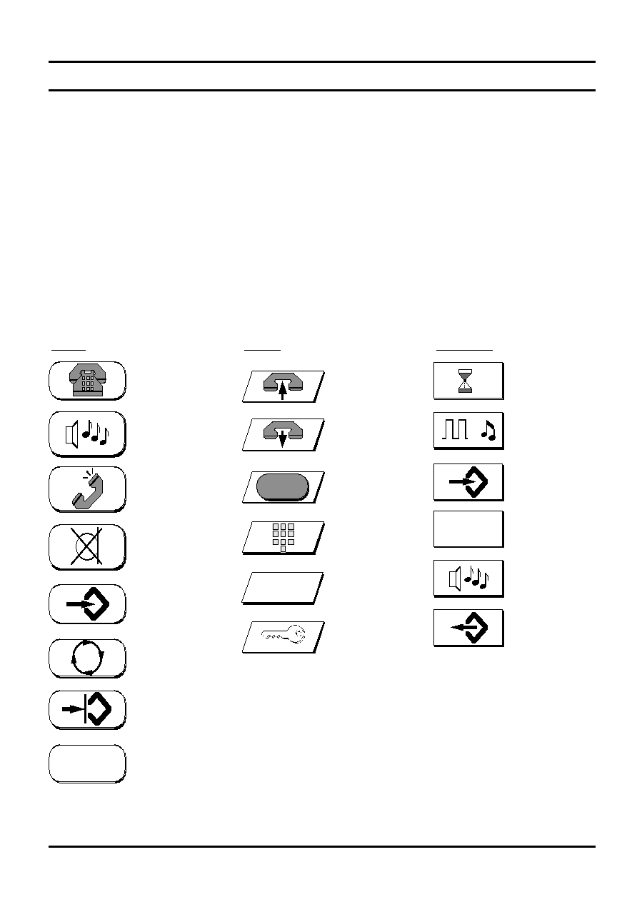
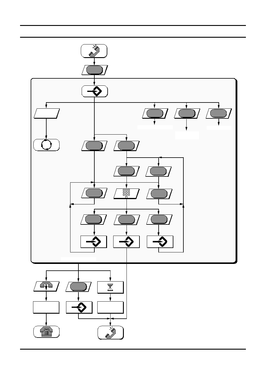
Setup Procedures
1
SET
5 or 6
*
Temporary MF Select
Programming Melody
ANY OTHER
ENTRY
40
sec
SET
Exit programme state
1590
LNR
Clear
Procedures
FALSE
LNR
ANY OTHER
ENTRY
LM Codes
022 or 023 or
033 or 036 or 037
LM Code
250
LNR
SET
022, 023 executed.
033, 036, 037
buffered
LNR
SET
LM Code
258
LNR
SET
ANY OTHER
SEQUENCE
LNR
LM Codes:
022 = no AP, no SC
023 = AP, no SC
033 = LD (MODE pin = V
DD
or Vss), GL
036 = MF, GL
037 = MF, FL
250 = Resets all settings to default, inhibits LNR
and memories
258 = Inhibits LNR and memories
Resets all
settings
to default
022, 023 executed.
033, 036, 037
buffered
M1-3
MEM
Storing Direct Numbers
Storing Indirect Numbers
Data Sheet
Rev. 3
10
AS2578 /B
March 1997
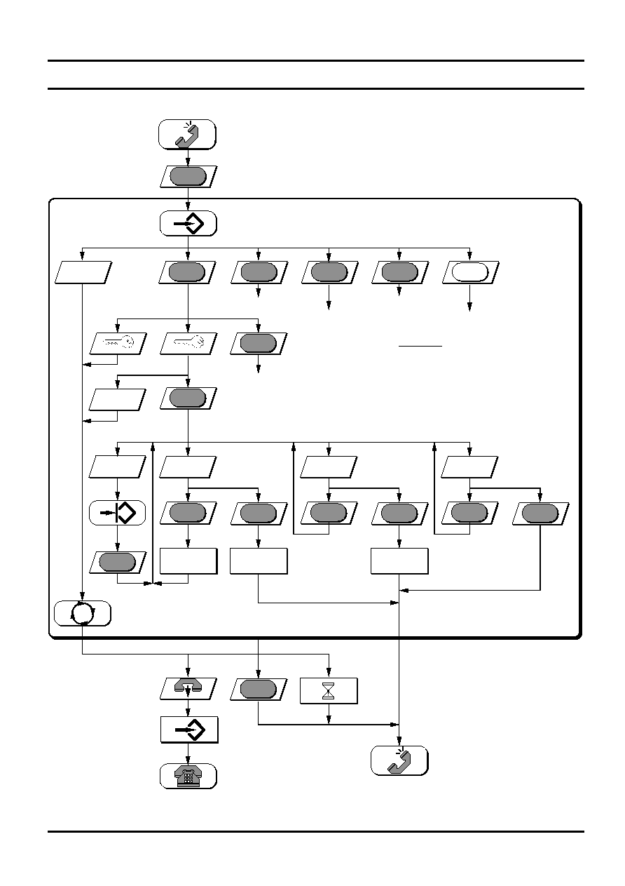
Clear Procedures
1
SET
5 or 6
*
Temporary MF Select
Programming Melody
ANY OTHER
ENTRY
40
sec
SET
Exit programme state
L N R
ANY OTHER
ENTRY
LM Code
258
L N R
SET
ANY OTHER
SEQUENCE
L N R
LM Codes:
258 = Inhibits LNR and memories
1590
Setup Procedures
M1-3
M E M
Storing Direct Numbers
Storing Indirect Numbers
Data Sheet
Rev. 3
11
AS2578 /B
March 1997
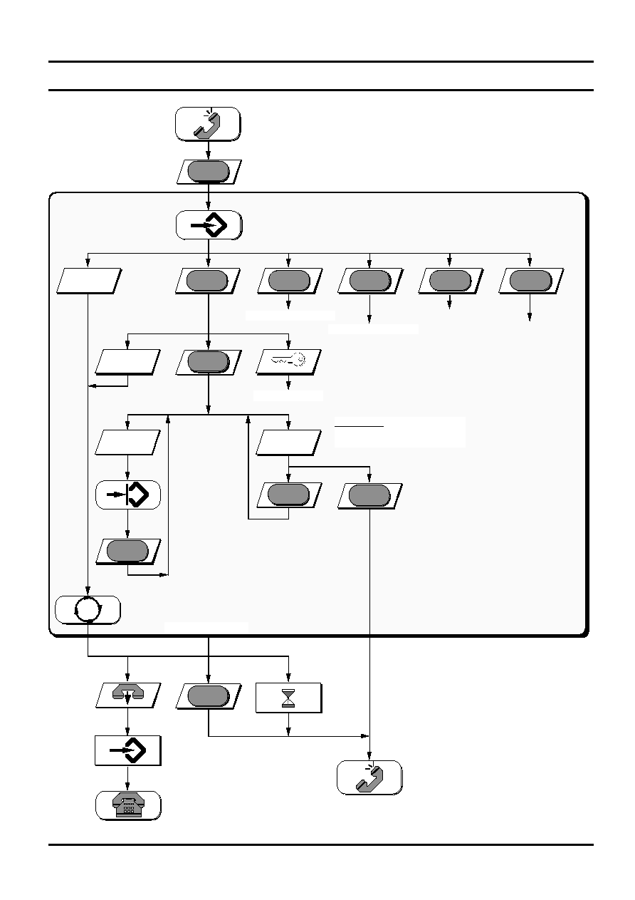
Programming Melody
1
S E T
5 or 6
*
Temporary MF Select
Setup Procedures
&
Clear Procedure
ANY OTHER
ENTRY
40
sec
S E T
Exit programme state
ANY OTHER
ENTRY
Key
1, 2, 3, or 4
S E T
LM Codes:
(5) 1 = Melody volume - 17.5 dB
(5) 2 = Melody volume - 11.1 dB
(5) 3 = Melody volume - 5.5 dB
(5) 4 = Melody volume 0 dB (default)
(6) 1 = Repetition rate 1
(6) 2 = Repetition rate 4 (default)
(6) 3 = Repetition rate 7
(6) 4 = Repetition rate 10
IGNORED
Executing
LM Code
M1-3
M E M
Storing Direct Numbers
Storing Indirect Numbers
Data Sheet
Rev. 3
12
AS2578 /B
March 1997
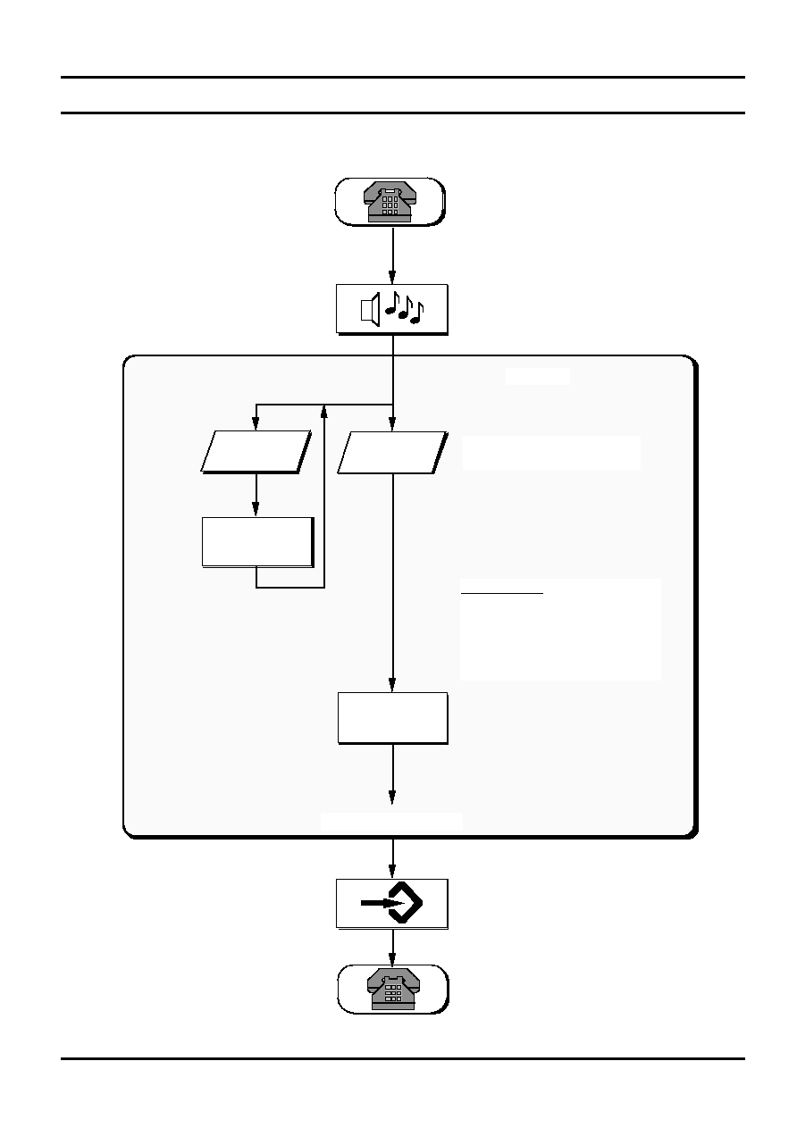
Programming Volume of Melody During Ringing
End of ringing
ANY OTHER
ENTRY
Key
1, 2, 3, or 4
LM Codes:
1 = Volume - 17.5 dB
2 = Volume - 11.5 dB
3 = Volume - 5.5 dB
4 = Volume 0 dB (default)
IGNORED
Executing
LM Code
RINGING
Only one change during a
ringing phase!
Data Sheet
Rev. 3
13
AS2578 /B
March 1997
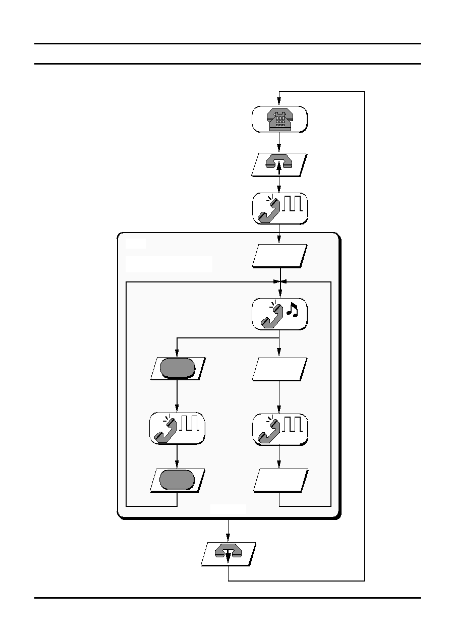
Temporary MF Select 1
(AP pin = open or low)
Set, * , Set
RAM
FIFO
Set, * , Set
FIFO
R
FIFO
2
1
R
D
Set, * , Set
FIFO
EXIT FIFO
Pressing any other key does not
change the state.
Data Sheet
Rev. 3
14
AS2578 /B
March 1997
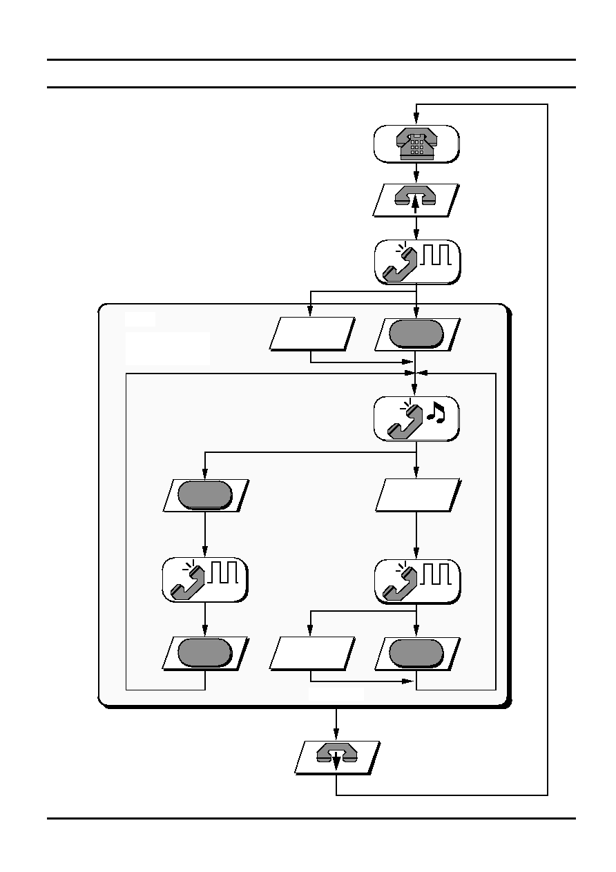
Temporary MF Select 2 (AS2578 only)
(AP pin = high)
RAM
FIFO
FIFO
R
FIFO
2
1
R
D
Set, * , Set
FIFO
EXIT FIFO
Pressing any other
key does not
change the state.
*
*
Set, * , Set
Set, * , Set
Data Sheet
Rev. 3
15
AS2578 /B
March 1997
Automatic Dialling
or
M1-3
0 - 9
Postdialled digits are not stored
but buffered in FIFO
L N R
M E M
Data Sheet
Rev. 3
16
AS2578 /B
March 1997
Storing Numbers
SET
5 or 6
*
Temporary MF Select
Programming
Melody
ANY OTHER
ENTRY
40
sec
SET
Exit programme state
SET
M1-3
1
Set Procedures
M E M
0 - 9
M1-3
M1-3
M E M
M E M
M1-3
CLEARS SAID
RAM MEMORY
LOCATION
CLEARS SAID
RAM MEMORY
LOCATION
Data Sheet
Rev. 3
17
AS2578 /B
March 1997
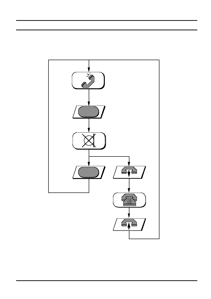
MUTE
Privacy Mute
Data Sheet
Rev. 3
19
AS2578 /B
March 1997
Electrical Characteristics
Absolute Maximum Ratings
Positive Supply Voltage ...................................................................................................................-0.3V
V
DD
7V
Input Current ................................................................................................................................................
±
25 mA
Digital Input Voltage ......................................................................................................V
SS
- 0.3V
V
IN
V
DD
+ 0.3V
Electrostatic Discharge (HBM) ........................................................................................................................
±
800V
Storage Temperature ......................................................................................................................-65
∞
C to +125
∞
C
Recommended Operating Conditions
Supply Voltage (except DTMF) .....................................................................................................2.2V
V
DD
5.5V
Supply Voltage (DTMF) .................................................................................................................2.5V
V
DD
5.5V
Oscillator Frequency ..................................................................................................................................3.58 MHz
Operating Temperature ....................................................................................................................- 25
∞
C to +70
∞
C
DC Characteristics (Default conditions: recommended operating conditions; outputs unloaded; V
DD
= 3.5V;
AP and MODE = Vss; unless otherwise specified))
Symbol
Parameter
Conditions
Min
Typ
Max
Units
I
DD0
Standby Current
HS = L; CE = L
0.1
µ
A
I
DD
Standby Current
HS = H; Osc. = 0
3.6
µ
A
I
DD
Operating Current
no tones
400
700
µ
A
I
DD
Operating Current
MF/melody
0.9
1.5
mA
V
IL
Input Voltage, Low
V
SS
0.2 V
DD
V
V
IH
Line Voltage, High
0.8 V
DD
V
DD
V
I
OL
Output Current, Sink
V
OL
= 0.4V
1.5
mA
I
OH
Output Current, Source
V
OH
= V
DD
- 0.4V
1
mA
R
HS
Pull-down Resistor
1
M
R
CE
Pull-down Resistor
1
M
AC Charateristics (Default conditions: recommended operating conditions)
Symbol
Parameter
Conditions
Min
Typ
Max
Units
t
S
Clock Startup Time
5
ms
t
D
Key Debounce Time
14.7
ms
t
HS
HS Debounce Time
14.7
ms
t
SU
Setup Time
100
ms
Continues...
Data Sheet
Rev. 3
20
AS2578 /B
March 1997
AC Characteristics Cont¥d
Symbol
Parameter
Conditions
Min
Typ
Max
Units
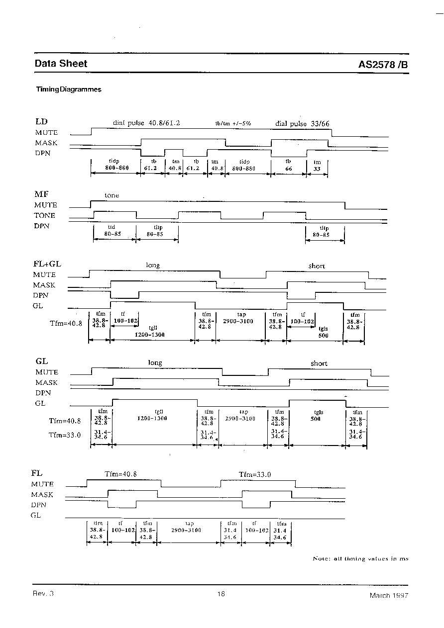
DTMF
V
MF
MF Tone Level
High group, R
L
= 15 k
-12.3
-10.8
-9.3
dBm
V
L-H
Preemphasis Low to High
R
L
= 15 k
2.0
2.4
2.8
dB
THD
Distortion (0.3 - 4 kHz)
R
L
= 15 k
, note 3
-23
dBr
t
TD
Tone Duration
Note 1
80
82.3
85
ms
t
ITP
Inter Tone Pause
Note 1
80
82.3
85
ms
t
TR
Tone Rise Time
Note 2
5
ms
t
TF
Tone Fall Time
Note 2
5
ms
LD
t
DR
Dial Rate
±
5%
10
pps
t
M/B
Make/Break Period
±
5%, MODE = low
40.8/61.2
ms
±
5%, MODE = high
33/66
ms
t
IDP
Inter Digit Pause
800
840
880
ms
t
MO
Mute Overhang
t
M
t
FD
Flash Duration
100
102
ms
t
GLS
Ground Loop, Short
R key
540 ms
495
500
505
ms
t
GLL
Ground Loop, Long
R key > 540 ms
1200
1250
1300
ms
t
AP
Automatic Pause
2.9
3.0
3.1
sec
Melody
V
MO
Melody Output
PDM
t
MD
Melody Delay
10
ms
F1
Frequency 1
770
800
830
Hz
F2
Frequency 2
1025
1067
1110
Hz
F3
Frequency 3
1280
1333
1385
Hz
t
DT
Detection Time
80
85
ms
t
TO
Detection Time-out
note 4
ms
f
MIN
Min. Detection Frequency
19
20
21
Hz
f
MAX
Max. Detection Frequency
58
59
60
Hz
Note 1: The values are valid during automatic dialling and are minimum values during manual dialling, i.e. the tones will
continue as long as the key is depressed.
Note 2: The rise time is the time from 10% of final value till the tone amplitude has reached 90 % of its final value.
Note 3: Relative to high group.
Note 4: The FCI circuit is reset by POR and on-hook. After a reset the FCI circuit is in a standby state. A positive edge on FCI
will start the 73 ms timer and the frequency discrimination is initiated. Whenever a period of the ring frequency is
missing, the timer is reset. When a valid ring signal is present for
73 ms, the melody generator is started and is
directly controlled by a valid signal from the FCI circuit. This condition will remain until a new reset.
Data Sheet
Rev. 3
21
AS2578 /B
March 1997
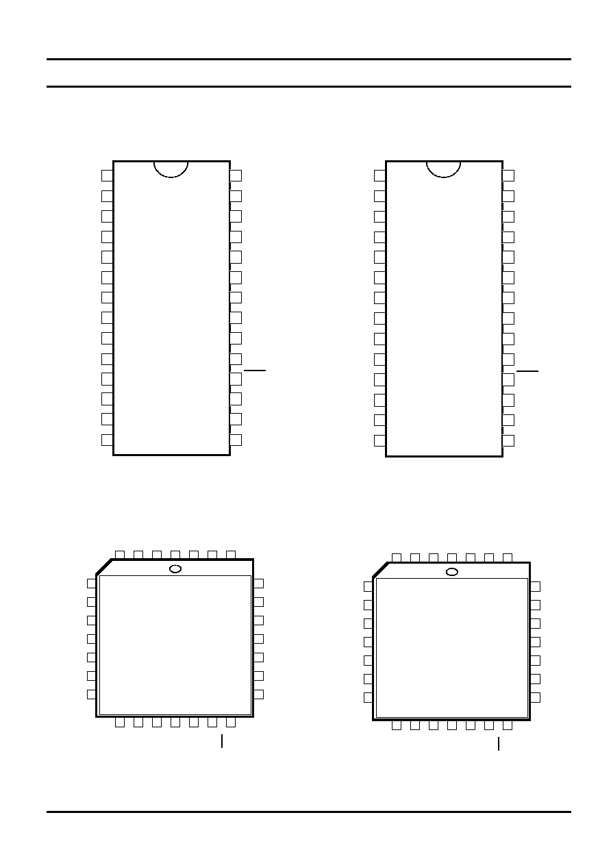
Pin Configurations
1
2
3
4
5
6
7
8
9
10
11
12
13
14
AS2578
RR
MV
AP
C5
R1
R2
R3
R4
V
DD
TONE
GL
DP
MASK
MUTE
C4
C3
C2
C1
HS
MODE
CE
Vss
OSC2
OSC1
SDA
SCL
FCI
MO
28
27
26
25
24
23
22
21
20
19
18
17
16
15
1
2
3
4
5
6
7
8
9
10
11
12
13
14
AS2578B
RR
MV
C5
C6
R1
R2
R3
R4
V
DD
TONE
GL
DP
MASK
MUTE
C4
C3
C2
C1
HS
MODE
CE
Vss
OSC2
OSC1
SDA
SCL
FCI
MO
28
27
26
25
24
23
22
21
20
19
18
17
16
15
HS
MODE
CE
Vss
OSC2
OSC1
GL
C6
R1
R2
R3
R4
V
DD
TONE
C1
C2
C3
C4
RR
MV
C5
SCL
FCI
MO
MUTE
MASK
DP
SDA
AS2578B
1
28 Pin PLCC
28 Pin DIP
HS
MODE
CE
Vss
OSC2
OSC1
GL
C5
R1
R2
R3
R4
V
DD
TONE
C1
C2
C3
C4
RR
MV
AP
SCL
FCI
MO
MUTE
MASK
DP
SDA
AS2578
1

Data Sheet
Rev. 3
22
AS2578 /B
March 1997
Ordering Information:
Part Number
Package
Pin 25
Pin 26
AS2578 P
28 pin DIP
C5
AP
AS2578 N
28 pin PLCC
C5
AP
AS2578B P
28 pin DIP
C6
C5
AS2578B N
28 pin PLCC
C6
C5
Applications:
For application support contact your local AMS sales office.
Copyright
©
1995-7, Austria Mikro Systeme International AG, Schloss Premst‰tten, 8141 Unterpremst‰tten, Austria. Trademarks
Registered
Æ
. All rights reserved. The material herein may not be reproduced, adapted, merged, translated, stored, or used without
the prior written consent of the copyright owner.
Devices sold by Austria Mikro Systeme are covered by the warranty and patent indemnification provisions appearing in its Term of
Sale. Austria Mikro Systeme makes no warranty, express, statutory, implied, or by description regarding the information set forth
herein or regarding the freedom of the described devices from patent infringement. Austria Mikro Systeme reserves the right to
change specifications and prices at any time and without notice. Therefore, prior to designing this product into a system, it is necessary
to check with Austria Mikro Systeme for current information. This product is intended for use in normal commercial applications.
Applications requiring extended temperature range, unusual environmental requirements, or high reliability applications, such as
military, medical life-support or life-sustaining equipment are specifically
not recommended without additional processing by Austria
Mikro Systeme for each application.