 | ÐлекÑÑоннÑй компоненÑ: AD8600 | СкаÑаÑÑ:  PDF PDF  ZIP ZIP |
Äîêóìåíòàöèÿ è îïèñàíèÿ www.docs.chipfind.ru
One Technology Way, P.O. Box 9106, Norwood. MA 02062-9106, U.S.A.
Tel: 617/329-4700
Fax: 617/326-8703
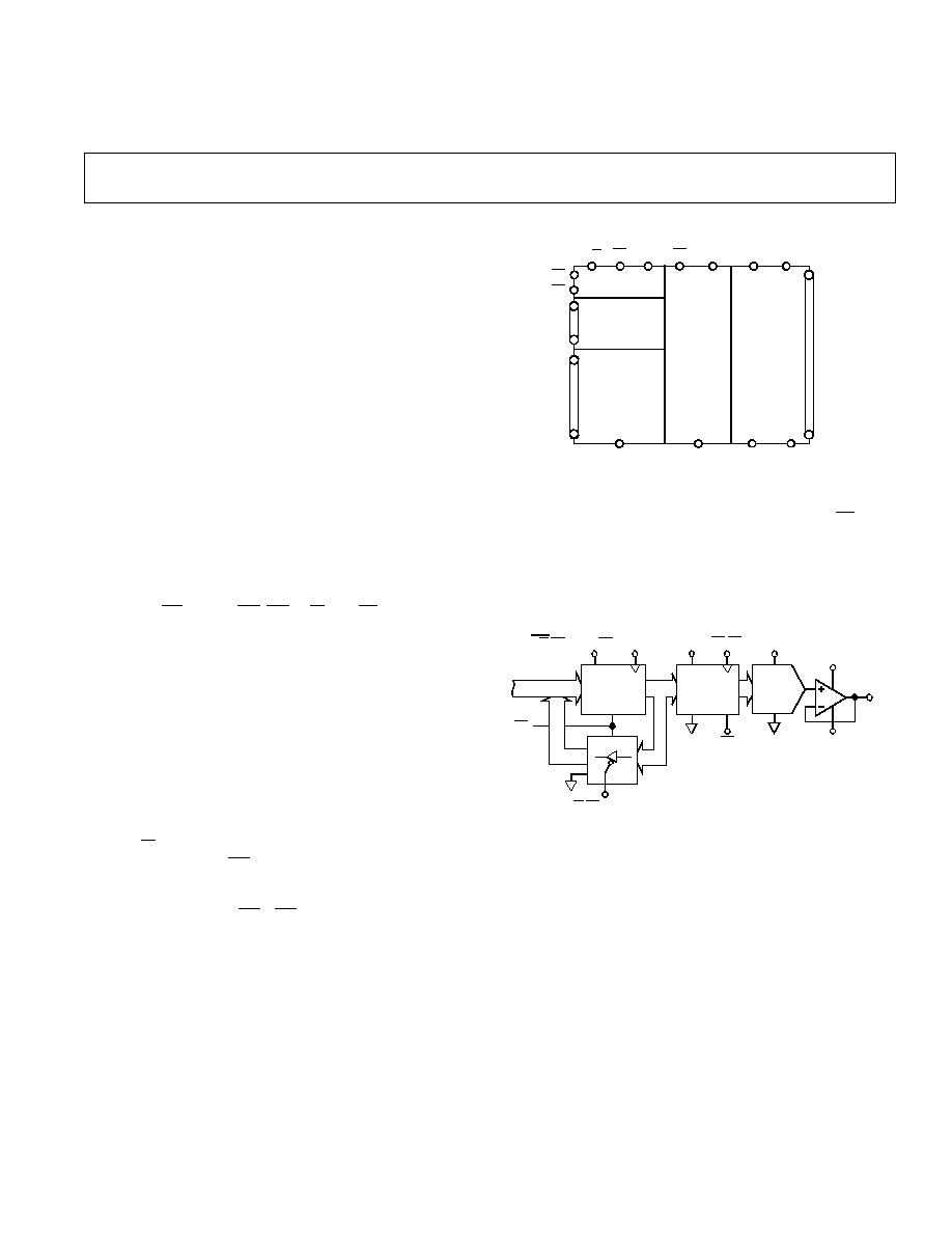
FUNCTIONAL BLOCK DIAGRAM
R/
W
V
DD1
LD
CONTROL
LOGIC
ADDRESS
DECODE
16 x 8
INPUT
REGISTERS
RS
V
DD2
V
REF
V
CC
16 x 8
DAC
REGISTERS
16
8-BIT
DAC
S
CS
EN
A3
A2
A1
A0
DB7
DB6
DB5
DB4
DB3
DB2
DB1
DB0
O0
O1
O2
O3
O4
O5
O6
O7
O8
O9
O10
O11
O12
O13
O14
O15
V
EE
D
GND1
D
GND2
DACGND
AD8600
REV. 0
Information furnished by Analog Devices is believed to be accurate and
reliable. However, no responsibility is assumed by Analog Devices for its
use, nor for any infringements of patents or other rights of third parties
which may result from its use. No license is granted by implication or
otherwise under any patent or patent rights of Analog Devices.
a
16-Channel, 8-Bit
Multiplying DAC
AD8600*
FEATURES
16 Independently Addressable Voltage Outputs
Full-Scale Set by External Reference
2
µ
s Settling Time
Double Buffered 8-Bit Parallel Input
High Speed Data Load Rate
Data Readback
Operates from Single +5 V
Optional
±
6 V Supply Extends Output Range
APPLICATIONS
Phased Array Ultrasound & Sonar
Power Level Setting
Receiver Gain Setting
Automatic Test Equipment
LCD Clock Level Setting
GENERAL DESCRIPTION
The AD8600 contains 16 independent voltage output digital-to-
analog converters that share a common external reference input
voltage. Each DAC has its own DAC register and input register
to allow double buffering. An 8-bit parallel data input, four ad-
dress pins, a CS select, a LD, EN, R/W, and RS provide the
digital interface.
The AD8600 is constructed in a monolithic CBCMOS process
which optimizes use of CMOS for logic and bipolar for speed
and precision. The digital-to-analog converter design uses volt-
age mode operation ideally suited to single supply operation.
The internal DAC voltage range is fixed at DACGND to V
REF
.
The voltage buffers provide an output voltage range that ap-
proaches ground and extends to 1.0 V below V
CC
. Changes in
reference voltage values and digital inputs will settle within
±
1 LSB in 2
µ
s.
Data is preloaded into the input registers one at a time after the
internal address decoder selects the input register. In the write
mode (R/W low) data is latched into the input register during
the positive edge of the EN pulse. Pulses as short as 40 ns can
be used to load the data. After changes have been submitted to
the input registers, the DAC registers are simultaneously up-
dated by a common load EN
×
LD strobe. The new analog out-
put voltages simultaneously appear on all 16 outputs.
*Patent pending.
At system power up or during fault recovery the reset (RS) pin
forces all DAC registers into the zero state which places zero
volts at all DAC outputs.
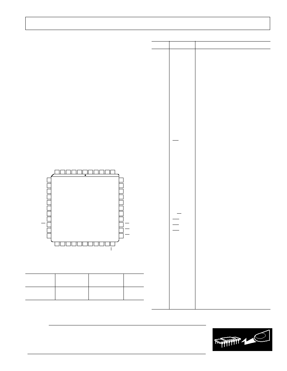
The AD8600 is offered in the PLCC-44 package. The device is
designed and tested for operation over the extended industrial
temperature range of 40
°
C to +85
°
C.
V
DD1
DACGND
R/
W
·
CS
·ADDRESS
RS
V
DD2
V
REF
V
CC
D
GND2
D
GND1
R-2R
DAC
LD
·
EN
V
EE
RS
R/
W
·
CS
·ADDR·
EN
O
X
DAC
REGISTER
INPUT
REGISTER
DB7...DB0
Figure 1. Equivalent DAC Channel

AD8600SPECIFICATIONS
SINGLE SUPPLY
Parameter
Symbol
Condition
Min
Typ
Max
Units
STATIC PERFORMANCE
1
Resolution
N
8
Bits
Relative Accuracy
2
INL
1
±
1/2
+1
LSB
Differential Nonlinearity
2
DNL
Guaranteed Monotonic
1
±
1/4
+1
LSB
Full-Scale Voltage
V
FS
Data = FF
H
2.480
2.490 2.500
V
Full-Scale Tempco
TCV
FS
Data = FF
H
±
20
ppm/
°
C
Zero Scale Error
V
ZSE
Data = 00
H
, RS = "0," T
A
= +25
°
C
+3.5
LSB
V
ZSE
Data = 00
H
, RS = "0"
+5
LSB
Reference Input Resistance
R
REF
Data = AB
H
1.2
2
k
ANALOG OUTPUT
Output Voltage Range
2
OVR
SS
V
REF
= +2.5 V
0.000
2.500
V
Output Current
I
OUT
Data = 80
H
±
2
mA
Capacitive Load
C
L
No Oscillation
50
pF
LOGIC INPUTS
Logic Input Low Voltage
V
IL
0.8
V
Logic Input High Voltage
V
IH
2.4
V
Logic Input Current
I
IL
10
µ
A
Logic Input Capacitance
3
C
IL
10
pF
LOGIC OUTPUTS
Logic Out High Voltage
V
OH
I
OH
= 0.4 mA
3.5
V
Logic Out Low Voltage
V
OL
I
OL
= 1.6 mA
0.4
V
AC CHARACTERISTICS
3
Slew Rate
SR
For
V
REF
or FS Code Change
4
7
V/
µ
s
Voltage Output Settling Time
2
t
S1
±
1 LSB of Final Value, Full-Scale Data Change
2
µ
s
Voltage Output Settling Time
2
t
S2
±
1 LSB of Final Value,
V
REF
= 1 V, Data = FF
H
2
µ
s
POWER SUPPLIES
Positive Supply Current
I
CC
V
IH
= 5 V, V
IL
= 0 V, No Load
24
35
mA
Logic Supply Currents
I
DD1&2
V
IH
= 5 V, V
IL
= 0 V, No Load
0.1
mA
Power Dissipation
P
DISS
V
IH
= 5 V, V
IL
= 0 V, No Load
120
175
mW
Power Supply Sensitivity
PSS
V
CC
=
±
5%
0.007
%/%
Logic Power Supply Range
V
DDR
4.75
5.25
V
Positive Power Supply Range
3
V
CCR
V
DD
7.0
V
NOTES
1
When V
REF
= 2.500 V, 1 LSB = 9.76 mV.
2
Single supply operation does not include the final 2 LSBs near analog ground. If this performance is critical, use a negative supply (V
EE
) pin of at least 0.7 V to
5.25 V. Note that for the INL measurement zero-scale voltage is extrapolated using codes 7
10
to 80
10
.
3
Guaranteed by design not subject to production test.
Specifications subject to change without notice.
REV. 0
2
(@ V
DD1
= V
DD2
= V
CC
= +5 V
±
5%, V
EE
= 0 V, V
REF
= +2.500 V, 40
°
C
T
A
+85
°
C, unless otherwise noted)

Parameter
Symbol
Condition
Min
Typ
Max
Units
STATIC PERFORMANCE
1
Resolution
N
8
Bits
Total Unadjusted Error
TUE
All Other DACs Loaded with Data = 55
H
1
±
3/4
+1
LSB
Relative Accuracy
INL
1
±
1/2
+1
LSB
Differential Nonlinearity
DNL
Guaranteed Monotonic
1
±
1/4
+1
LSB
Full-Scale Voltage
V
FS
Data = FF
H
, V
REF
= +3.5 V
3.473
3.486
3.500
V
Full-Scale Voltage Error
V
FSE
Data = FF
H
, V
REF
= +3.5 V
1
+1
LSB
Full-Scale Tempco
TCV
FS
Data = FF
H
, V
REF
= +3.5 V
±
20
ppm/
°
C
Zero Scale Error
V
ZSE
Data = 00
H
, RS = "0," T
A
= +25
°
C
2
±
1
+2
mV
Zero Scale Error
V
ZSE
Data = 00
H
, All Other DACs Data = 00
H
1
+1
LSB
Zero Scale Error
V
ZSE
Data = 00
H
, All Other DACs Data = 55
H
±
1/2
LSB
Zero Scale Tempco
TCV
ZS
Data = 00
H
, V
CC
= +5 V, V
EE
= 5 V
±
10
µ
V/
°
C
Reference Input Resistance
R
REF
Data = AB
H
1.2
2
k
Reference Input Capacitance
2
C
REF
Data = AB
H
240
pF
ANALOG OUTPUT
Output Voltage Range
OVR
1
V
REF
= +3.5 V
0.000
3.500
V
Output Voltage Range
2
OVR
2
V
CC
= V
DD2
= +7 V, V
EE
= 0.7 V, V
REF
= 5 V
0.000
5.000
V
Output Current
I
OUT
Data = 80
H
±
2
mA
Capacitive Load
2
C
L
No Oscillation
50
pF
LOGIC INPUTS
Logic Input Low Voltage
V
IL
0.8
V
Logic Input High Voltage
V
IH
2.4
V
Logic Input Current
I
IL
10
µ
A
Logic Input Capacitance
2
C
IL
10
pF
LOGIC OUTPUTS
Logic Out High Voltage
V
OH
I
OH
= 0.4 mA
3.5
V
Logic Out Low Voltage
V
OL
I
OL
= 1.6 mA
0.4
V
AC CHARACTERISTICS
2
Reference In Bandwidth
BW
3 dB Frequency, V
REF
= 2.5 V
DC
+ 0.1 V
AC
500
kHz
Slew Rate
SR
For
V
REF
or FS Code Change
4
7
V/
µ
s
Voltage Noise Density
e
N
f = 1 kHz, V
REF
= 0 V
46
nV/
Hz
Digital Feedthrough
FT
Digital Inputs to DAC Outputs
10
nVs
Voltage Output Settling Time
3
t
S1
±
1 LSB of Final Value, FS Data Change
1
2
µ
s
Voltage Output Settling Time
3
t
S2
±
1 LSB of Final Value,
V
REF
= 1 V, Data = FF
H
1
2
µ
s
POWER SUPPLIES
Positive Supply Current
I
CC
V
IH
= 5 V, V
IL
= 0 V, V
EE
= 5 V, No Load
22
35
mA
Negative Supply Current
I
EE
V
IH
= 5 V, V
IL
= 0 V, V
EE
= 5 V, No Load
22
35
mA
Logic Supply Currents
I
DD1&2
V
IH
= 5 V, V
IL
= 0 V, V
EE
= 5 V, No Load
0.1
mA
Power Dissipation
4
P
DISS
V
IH
= 5 V, V
IL
= 0 V, V
EE
= 5 V, No Load
225
350
mW
Power Supply Sensitivity
PSS
V
CC
&
V
EE
=
±
5%
0.007
%/%
Logic Power Supply Range
V
DDR
4.75
5.25
V
Pos Power Supply Range
2
V
CCR
V
DD
7.0
V
Neg Power Supply Range
2
V
EER
5.25
0.0
V
NOTES
1
When V
REF
= +3.500 V, 1 LSB = 13.67 mV.
2
Guaranteed by design not subject to production test.
3
Settling time test is performed using R
L
= 50 k
and C
L
= 35 pF.
4
Power Dissipation is calculated using 5 V
×
(I
DD
+ |I
SS
| + I
DD1
+ I
DD2
).
Specifications subject to change without notice.
DUAL SUPPLY
(@ V
DD1
= V
DD2
= V
CC
= +5 V
±
5%, V
EE
= 5 V
±
5%, V
REF
= +3.500 V, 40
°
C
T
A
+85
°
C, unless otherwise noted)
AD8600
REV. 0
3
REV. 0
4
AD8600
ELECTRICAL CHARACTERISTICS
Parameter
Symbol
Condition
Min
Typ
Max
Units
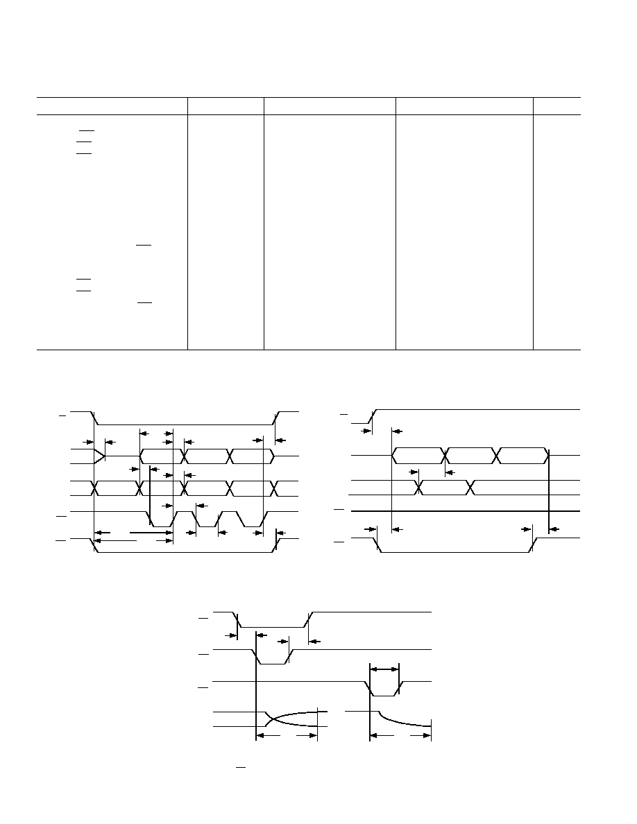
INTERFACE TIMING
1, 2
Clock (EN) Frequency
f
CLK
Data Loading
12.5
MHz
Clock (EN) High Pulse Width
t
CH
40
ns
Clock (EN) LowPulse Width
t
CL
40
ns
Data Setup Time
t
DS
40
ns
Data Hold Time
t
DH
10
ns
Address Setup Time
t
AS
0
ns
Address Hold Time
t
AH
0
ns
Valid Address to Data Valid
t
AD
160
ns
Load Enable Setup Time
t
LS
0
ns
Load Enable Hold Time
t
LH
0
ns
Read/Write to Clock (EN)
t
RWC
30
ns
Read/Write to DataBus Hi-Z
t
RWZ
120
ns
Read/Write to DataBus Active
t
RWD
120
ns
Clock (EN) to Read/Write
t
TWH
0
ns
Clock (EN) to Chip Select
t
TCH
0
ns
Chip Select to Clock (EN)
t
CSC
30
ns
Chip Select to Data Valid
t
CSD
120
ns
Chip Select to DataBus Hi-Z
t
CSZ
150
ns
Reset Pulse Width
t
RS
25
ns
NOTES
1
Guaranteed by design not subject to production test.
2
All logic input signals have maximum rise and fall times of 2 ns.
Specifications subject to change without notice.
Figure 3. Readback Timing
Figure 2. Write Timing
(@ V
DD1
= V
DD2
= V
CC
= +5 V
±
5%, V
EE
= 5 V, V
REF
= +3.500 V, 40
°
C
T
A
+85
°
C,
unless otherwise noted)
t
RWZ
t
DH
t
TWH
HIGH-Z
t
AS
t
AH
t
CH
t
CL
t
TCH
R/
W
DATA
ADDR
EN
CS
t
CSC
t
RWC
t
DS
Figure 4. Write to DAC Register & Voltage Output Settling
Timing (CS= High, Prevents Input Register Changes)
t
LS
t
LH
t
S1
t
RS
OUT
t
S1
EN
RS
LD
t
RWD
HIGH -Z
t
AD
t
CSZ
t
CSD
R/
W
DATA
ADDR
EN
CS
AD8600
REV. 0
5
PIN DESCRIPTION
Pin No.
Name
Description
1
NC
No Connection
2
V
REF
Reference input voltage common
to all DACs.
3
DACGND
DAC Analog Ground Return. Sets
analog zero-scale voltage.
4
V
CC
Output Amplifier Positive Supply
5
V
EE
Output Amplifier Negative Supply
6
O7
DAC Channel Output No. 7
7
O6
DAC Channel Output No. 6
8
O5
DAC Channel Output No. 5
9
O4
DAC Channel Output No. 4
10
O3
DAC Channel Output No. 3
11
O2
DAC Channel Output No. 2
12
O1
DAC Channel Output No. 1
13
O0
DAC Channel Output No. 0
14
V
DD1
Digital Logic Power Supply
15
RS
Active Low Reset Input Pin
16
DB0
Data Bit Zero I/O (LSB)
17
DB1
Data Bit I/O
18
DB2
Data Bit I/O
19
DB3
Data Bit I/O
20
DB4
Data Bit I/O
21
DB5
Data Bit I/O
22
DB6
Data Bit I/O
23
DB7
Most Significant Data Bit I/O (MSB)
24
A0
Address Bit Zero (LSB)
25
A1
Address Bit
26
A2
Address Bit
27
A3
Most Significant Addr Bit (MSB)
28
R/W
Read/Write Select Control Input
29
EN
Active Low Enable Clock Strobe
30
CS
Chip Select Input
31
LD
DAC Register Load Strobe
32
DGND1
Digital Ground Input No. 1
33
O15
DAC Channel Output No. 15
34
O14
DAC Channel Output No. 14
35
O13
DAC Channel Output No. 13
36
O12
DAC Channel Output No. 12
37
O11
DAC Channel Output No. 11
38
O10
DAC Channel Output No. 10
39
O9
DAC Channel Output No. 9
40
O8
DAC Channel Output No. 8
41
V
EE
Output Amplifier Negative Supply
42
V
CC
Output Amplifier Positive Supply
43
DGND2
Digital Ground Input No. 2
44
V
DD2
DAC Analog Supply Voltage
WARNING!
ESD SENSITIVE DEVICE
CAUTION
ESD (electrostatic discharge) sensitive device. Electrostatic charges as high as 4000 V readily
accumulate on the human body and test equipment and can discharge without detection.
Although the AD8600 features proprietary ESD protection circuitry, permanent damage may
occur on devices subjected to high energy electrostatic discharges. Therefore, proper ESD
precautions are recommended to avoid performance degradation or loss of functionality.
ABSOLUTE MAXIMUM RATINGS
(T
A
= +25
°
C unless otherwise noted)
V
DD1
(Digital Supply) to GND . . . . . . . . . . . . . . 0.3 V, +7 V
V
DD2
(DAC Buffer/Driver Supply) . . . . . . . . . . . . 0.3 V, +7 V
V
CC
(Analog Supply) to GND . . . . . . . . . . . . . . . 0.3 V, +7 V
V
EE
(Analog Supply) to GND . . . . . . . . . . . . . . . +0.3 V, 7 V
V
REF
to GND . . . . . . . . . . . . . . . . . . . . . . 0.3 V, V
CC
+ 0.3 V
V
DD2
to V
REF
. . . . . . . . . . . . . . . . . . . . . . . . . . . . . . . . . 0.3 V
V
OUT
to GND . . . . . . . . . . . . . . . . . . . . . . . . . . . . . . . . . V
CC
Short Circuit Duration
V
OUT
to GND or Power Supplies
1
. . . . . . . . . . . . . . .
Continuous
Digital Input/Output Voltage to GND . . . 0.3 V, V
DD
+ 0.3 V
Thermal ResistanceTheta Junction-to-Ambient (
JA
)
PLCC-44 . . . . . . . . . . . . . . . . . . . . . . . . . . . . . . . . 47
°
C/W
Package Power Dissipation . . . . . . . . . . . . . . . . (T
J
T
A
)/
JA
Maximum Junction Temperature T
J
max . . . . . . . . . . . 150
°
C
Operating Temperature Range . . . . . . . . . . . . 40
°
C to +85
°
C
Storage Temperature Range . . . . . . . . . . . . 65
°
C to +150
°
C
Lead Temperature (Soldering, 10 sec) . . . . . . . . . . . . +300
°
C
NOTE
1
No more than four outputs may be shorted to power or GND simultaneously.
PIN CONFIGURATION
NC = NO CONNECT
O9
O10
O13
O14
O15
O11
O12
O6
O5
O2
O1
O0
O4
O3
O7
V
EE
V
REF
NC
V
DD2
V
CC
DB2
DB3
DB6
DB7
A0
DB4
DB5
DACGND
V
CC
V
EE
O8
A2
A3
R/
W
A1
DGND2
LD
CS
EN
DGND1
RS
DB0
DB1
V
DD1
44
1
2
6
4
5
21
24
23
22
18
20
19
39
38
35
34
33
37
36
3
7
8
11
12
13
9
10
40
41
42
25
28
27
26
43
31
30
29
32
15
16
17
14
TOP VIEW
(Not to Scale)
AD8600
ORDERING GUIDE
Package
Package
Model
Temperature
Description
Option
AD8600AP
40
°
C to +85
°
C 44-Lead PLCC
P-44A
AD8600Chips
+25
°
C
Die*
*For die specifications contact your local Analog Devices sales office.
The AD8600 contains 5782 transistors.
REV. 0
6
AD8600
TRANSFER EQUATIONS
Output Voltage
O
i
= D
×
V
REF
256
where i is the DAC channel number and D is the decimal value
of the DAC register data.
Table I. Truth Table
EN
R/W
CS LD
RS
Operation
Write to DAC Register
X
H
L
H
Update DAC Register
L
X
H
H
Update DAC Register
+
X
H
L
H
Latches DAC Register
L
X
H
+
H
Latches DAC Register
L
L
L
L
H
DAC Register Transparent
Write to Input Register
L
L
L
H
H
Load Data to Input Register at
Decoded Address
+
L
L
H
H
Latches Data in Input Register at
Decoded Address
L
L
+
H
H
Latches Data in Input Register at
Decoded Address
Readback Input Registers
X
H
L
H
H
Input Register Readback (Data
Access)
X
H
+
H
H
Hi-Z Readback Disconnects from
Bus
X
X
H
X
X
Hi-Z on Data Bus
Reset
X
X
X
X
L
Clear All Registers to Zero,
V
OUT
= 0 V
X
X
H
H
+
Latches All Registers to Zero
L
X
L
H
+
CS
= Low; Input Register Ready
for R/W, DAC Register Latched
to Zero
NOTES
1
+ symbol means positive edge of control input line.
2
symbol means negative edge of control input line.
Decoded DAC Register
O
i
= A
where A is the decimal value of the decoded address bits A3,
A2, A1, A0 (LSB).
Address, CS, R/W and data inputs should be stable prior to acti-
vation of the active low EN input. Input registers are transpar-
ent when EN is low. When EN returns high, data is latched into
the decoded input register. When the load strobe LD and EN
pins are active low, all input register data is transferred to the
DAC registers. The DAC registers are transparent while they
are enabled.
Table II. Address Decode Table
A3
A2
A1
A0
Addr
DAC
(MSB)
(LSB)
Code
Updated
(Binary)
(Hex)
0
0
0
0
0
O0
0
0
0
1
1
O1
0
0
1
0
2
O2
0
0
1
1
3
O3
0
1
0
0
4
O4
0
1
0
1
5
O5
0
1
1
0
6
O6
0
1
1
1
7
O7
1
0
0
0
8
O8
1
0
0
1
9
O9
1
0
1
0
A
O10
1
0
1
1
B
O11
1
1
0
0
C
O12
1
1
0
1
D
O13
1
1
1
0
E
O14
1
1
1
1
F
O15
Typical Performances CharacteristicsAD8600
REV. 0
7
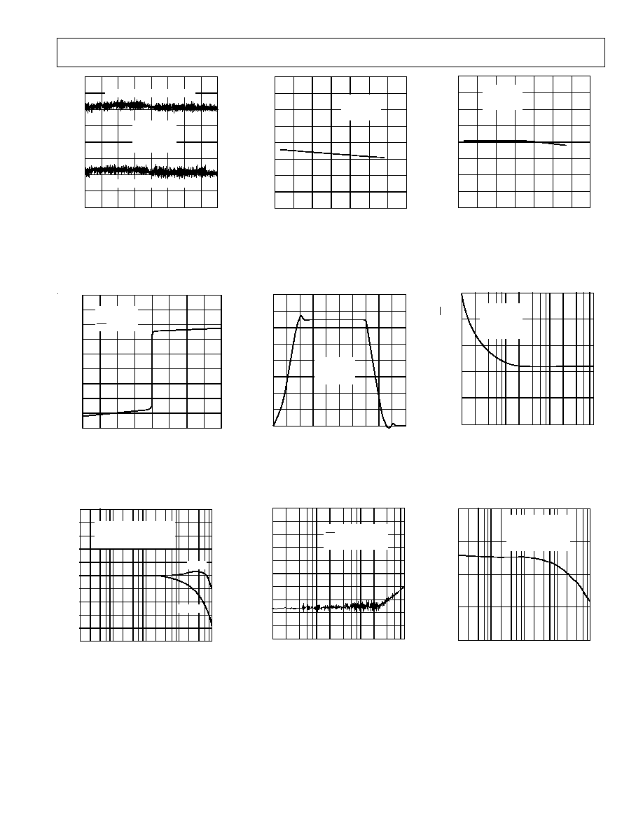
0
1/2
+1/2
1/2
0
+1/2
256
0
192
128
64
DIGITAL INPUT CODE Decimal
LINEARITY ERROR LSB
DACs 0007 SUPERIMPOSED
DACs 08015 SUPERIMPOSED
V
CC
= +5V
V
EE
= 5V
V
REF
= +3.5V
T
A
= +25
°
C
Figure 5. Linearity Error vs.
Digital Code
V
OUT
Volts
I
OUT
mA
10
15
5
5
0
15
10
4
3
2
0
1
1
2
3
4
V
CC
= +5V
V
EE
= 5V
RS
= 0
Figure 8. Output Current vs.
Voltage
0
0
1k
10k
10M
1M
100k
90
45
15
10
5
FREQUENCY Hz
GAIN dB
PHASE Degrees
PHASE
GAIN
V
IN
= 100mV p-p + 2.5V
DC
CODE = FF
H
T
A
= +25
°
C
Figure 11. Gain & Phase vs.
Frequency
3.47
3.48
3.49
3.50
125
25
50
100
75
50
25
0
TEMPERATURE
°
C
FULL-SCALE OUTPUT Volts
V
CC
= +5V
V
EE
= 5V
V
REF
= 3.5V
Figure 6. Full-Scale Voltage vs.
Temperature
1
2
3
0
4
OUTPUT AMPLITUDE Volts
TIME 250ns/DIV
V
CC
= +5V
V
EE
= 5V
V
REF
= 3.5V
Figure 9. Full-Scale Settling Time
100
1k
100k
10k
FREQUENCY Hz
V
IN
= 2V p-p + 1V
DC
RS
= 0
T
A
= +25
°
C
FEEDTHROUGH dB
0
20
40
60
80
100
Figure 12. AC Feedthrough vs.
Frequency
125
25
50
8
4
2
0
4
100
75
50
25
0
TEMPERATURE
°
C
ZERO-SCALE mV
V
CC
= +5V
V
EE
= 5V
V
REF
= 3.5V
Figure 7. Zero-Scale Voltage vs.
Temperature
FREQUENCY Hz
10
100
10k
1k
100
80
0
60
40
20
NOISE VOLTAGE DENSITY nV/
Hz
V
CC
= +5V
V
EE
= 5V
V
REF
= 0V
T
A
= +25
°
C
Figure 10. Voltage Noise Density vs.
Frequency
40
30
20
50
60
1k
10k
100
10
100k
FREQUENCY Hz
PSRR dB
V
CC
= 100mV p-p
T
A
= +25
°
C
CODE = 00
H
V
EE
= 5V
Figure 13. PSRR vs. Frequency
REV. 0
8
AD8600
*Patent Pending.
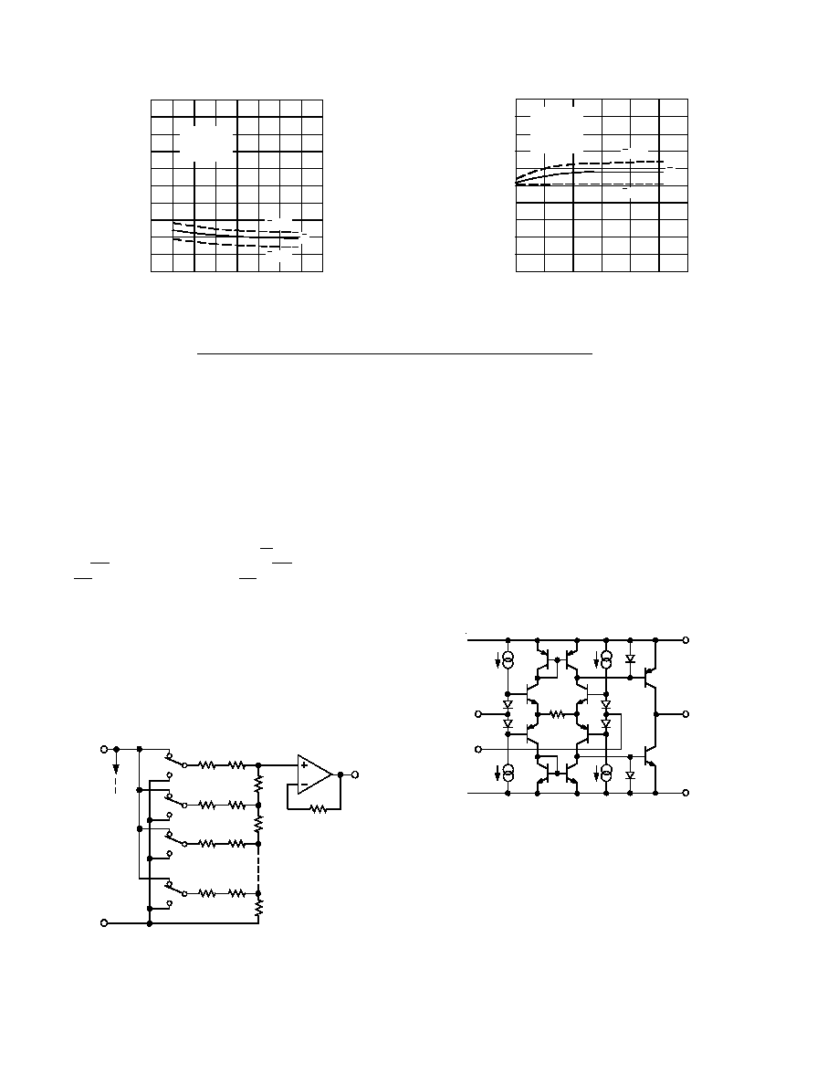
Figure 14. Supply Current vs. Temperature
Figure 15. Output Voltage Drift
Accelerated by Burn-In
SUPPLY CURRENT mA
TEMPERATURE
°
C
20
15
16
18
17
19
125
50
75
100
25
50
25
0
75
V
CC
= +5V
V
EE
= 5V
V
REF
= 3.5V
+ 3
- 3
T = HOURS OF OPERATION AT +125
°
C
CHANGE IN ZERO SCALE mV
1200
200
0
1000
600
800
400
+ 3
- 3
V
CC
= +5V
V
EE
= 5V
V
REF
= 3.5V
CODE = 00
H
2
4
0
2
4
1
3
5
1
3
5
Operation
The AD8600 is a 16-channel voltage output, 8-bit digital to
analog converter. The AD8600 operates from a single +5 V
supply, or for a wider output swing range, the part can operate
from dual supplies of
±
5 V or
±
6 V or a single supply of +7 V.
The DACs are based upon a unique R-2R ladder structure*
that removes the possibility of current injection from the refer-
ence to ground during code switching. Each of the 8-bit DACs
has an output amplifier to provide 16 low impedance outputs.
With a single external reference, 16 independent dc output lev-
els can be programmed through a parallel digital interface. The
interface includes 4 bits of address (A0A3), 8 bits of data
(DB0DB7), a read/write select pin (R/W), an enable clock
strobe (EN), a DAC register load strobe (LD), and a chip select
pin (CS). Additionally a reset pin (RS) is provided to asynchro-
nously reset all 16 DACs to 0 V output.
D/A Converter Section
The internal DAC is an 8-bit voltage mode device with an out-
put that swings from DACGND to the external reference volt-
age, V
REF
. The equivalent schematic of one of the DACs is
shown in Figure 16. The DAC uses an R-2R ladder to ensure
accuracy and linearity over the full temperature range of the part.
The switches shown are actually N and P-channel MOSFETs to
allow maximum flexibility and range in the choice of reference
R
R
R
V
OUT
R
R
R
2R
R
R
R
R
R
TO 15
DACs
V
REF
DACGND
*R = 30k
TYPICALLY
Figure 16. Equivalent Schematic of Analog Channel
voltage. The switches' low ON resistance and matching is im-
portant in maintaining the accuracy of the R-2R ladder.
Amplifier Section
The output of the DAC ladder is buffered by a rail-to-rail out-
put amplifier. This amplifier is configured as a unity gain fol-
lower as shown in Figure 16. The input stage of the amplifier
contains a PNP differential pair to provide low offset drift and
noise. The output stage is shown in Figure 17. It employs
complementary bipolar transistors with their collectors con-
nected to the output to provide rail-to-rail operation. The NPN
transistor enters into saturation as the output approaches the
negative rail. Thus, in single supply, the output low voltage is
limited by the saturation voltage of the transistor. For the tran-
sistors used in the AD8600, this is approximately 40 mV. The
AD8600 was not designed to swing to the positive rail in con-
trast to some of ADI's other DACs (for example, the AD8582).
The output stage of the amplifier is actually capable of swinging
to the positive rail, but the input stage limits this swing to ap-
proximately 1.0 V below V
CC
.
V
EE
V
OUT
V
CC
Figure 17. Equivalent Analog Output Circuit
During normal operation, the output stage can typically source
and sink
±
1 mA of current. However, the actual short circuit
current is much higher. In fact, each DAC is capable of sourc-
ing 20 mA and sinking 8 mA during a short condition. The
absolute maximum ratings state that, at most, four DACs can
be shorted simultaneously. This restriction is due to current
densities in the metal traces. If the current density is too high,
voltage drops in the traces will cause a loss in linearity perfor-
mance for the other DACs in the package. Thus to ensure long-
term reliability, no more than four DACs should be shorted
simultaneously.
AD8600
REV. 0
9
Power Supply and Grounding Considerations
The low power consumption of the AD8600 is a direct result of
circuit design optimizing using a CBCMOS process. The over-
all power dissipation of 120 mW translates to a total supply cur-
rent of only 24 mA for 16 DACs. Thus, each DAC consumes
only 1.5 mA. Because the digital interface is comprised entirely
of CMOS logic, the power dissipation is dependent upon the
logic input levels. As expected for CMOS, the lowest power
dissipation is achieved when the input level is either close to
ground or +5 V. Thus, to minimize the power consumption,
CMOS logic should be used to interface to the AD8600.
The AD8600 has multiple supply pins. V
CC
(Pins 4 and 42) is
the output amplifiers' positive supply, and V
EE
(Pins 5 and 41)
the amplifiers' negative supply. The digital input circuitry is
powered by V
DD1
(Pin 14), and finally the DAC register and R-
2R ladder switches are powered by V
DD2
(Pin 44). To minimize
noise feedthrough from the supplies, each supply pin should be
decoupled with a 0.1
µ
F ceramic capacitor close to the pin.
When applying power to the device, it is important for the digi-
tal supply, V
DD2
, to power on before the reference voltage and
for V
REF
to remain less than 0.3 V above V
DD2
during normal
operation. Otherwise, an inherent diode will energize, and it
could damage the AD8600.
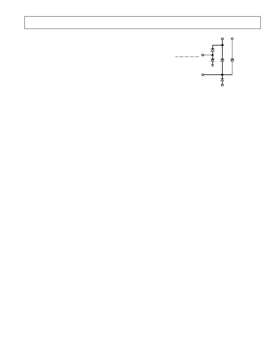
In order to improve ESD resistance, the AD8600 has several
ESD protection diodes on its various pins. These diodes shunt
ESD energy to the power supplies and protect the sensitive ac-
tive circuitry. During normal operation, all the ESD diodes are
reversed biased and do not affect the part. However, if overvolt-
ages occur on the various inputs, these diodes will energize. If
the overvoltage is due to ESD, the electrical spike is typically
short enough so that the part is not damaged. However, if the
overvoltage is continuous and has sufficient current, the part
could be damaged. To protect the part, it is important not to
forward bias any of the ESD protection diodes during normal
operation or during power up. Figure 18 shows the location of
these diodes. For example, the digital inputs have diodes con-
nected to V
CC
and from DGND1. Thus, the voltage on any
digital input should never exceed the analog supply or drop be-
low ground, which is also indicated in the absolute maximum
ratings.
DGND1
V
CC
V
DD2
DACGND
V
REF
ALL DIGITAL INPUTS
(A0A3, DB0DB7)
(R/
W
,
CS
,
EN
,
LD
,
RS
)
Figure 18. ESD Protection Diode Locations
Attention should be paid to the ground pins of the AD8600 to
ensure that noise is not introduced to the output. The pin la-
beled DACGND (Pin 3) is actually the ground for the R-2R
ladder, and because of this, it is important to connect this pin to
a high quality analog ground. Ideally, the analog ground should
be an actual ground plane. This helps create a low impedance,
low noise ground to maintain accuracy in the analog circuitry.
The digital ground pins (DGND1 at Pin 32 and DGND2 at
Pin 43) provide the ground reference for the internal digital cir-
cuitry and latches. The first thought may be to connect both of
these pins to the system digital ground. However, this is not the
best choice because of the high noise typically found on a
system's digital ground. This noise can feed through to the out-
put through the DAC's ground pins. Instead, DGND1 and
DGND2 should be connected to the analog ground plane. The
actual switching current in these pins is small and should not
degrade the analog ground.
5 V Output Swing
The output swing is limited to 1.0 V below the positive supply.
This gives a maximum output of +4.0 V on a +5 V supply. To
increase the output range, the analog supply, V
CC
, and the DAC
ladder supply, V
DD2
, can be increased to +7 V. This allows an
output of +5 V with a 5 V reference. V
DD1
should remain at
+5 V to ensure that the input logic levels do not change.
Reference Input Considerations
The AD8600 is designed for one reference to drive all 16 DACs.
The reference pin (V
REF
) is connected directly to the R-2R lad-
ders of each DAC. With 16 DACs in parallel, the input imped-
ance is typically 2 k
and a minimum of 1.2 k
. The input
resistance is code dependent. Thus, the chosen reference device
must be able to drive this load. Some examples of +2.5 V refer-
ences that easily interface to the AD8600 are the REF43,
AD680, and AD780. The unique architecture ensures that the
reference does not have to supply "shoot through" current,
which is a condition in some voltage mode DACs where the ref-
erence is momentarily connected to ground through the CMOS
switches. By eliminating this possibility, all 16 DACs in the
AD8600 can easily be driven from a single reference.
REV. 0
10
AD8600
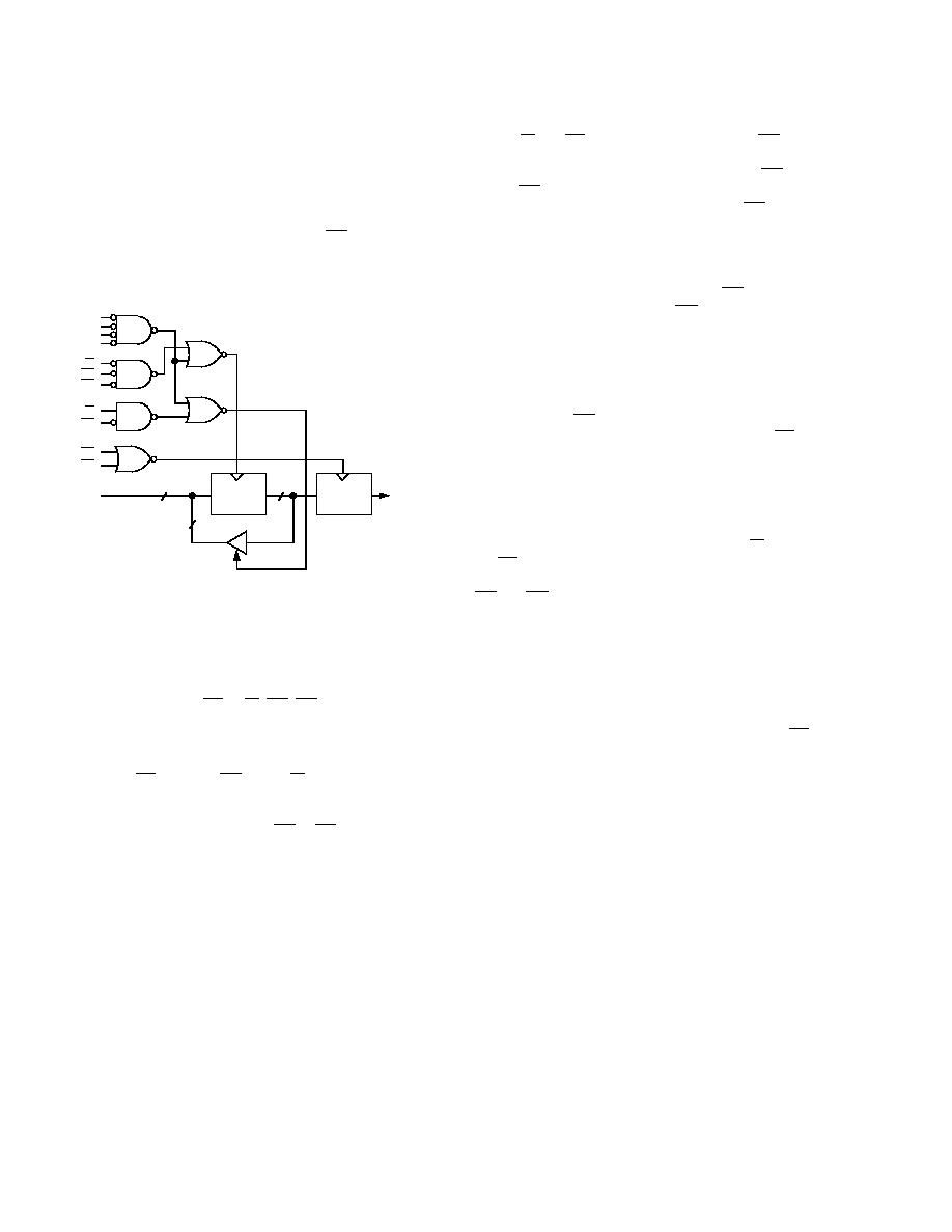
Interface Timing and Control
The AD8600 employs a double buffered DAC structure with
each DAC channel having a unique input register and DAC reg-
ister as shown in the diagram entitled "Equivalent DAC Chan-
nel" on the first page of the data sheet. This structure allows
maximum flexibility in loading the DACs. For example, each
DAC can be updated independently, or, if desired, all 16 input
registers can be loaded, followed by a single LD strobe to up-
date all 16 DACs simultaneously. An additional feature is the
ability to read back from the input register to verify the DAC's
data.
A0
A1
A2
A3
R/
W
EN
CS
R/
W
CS
LD
EN
N4
N3
N2
N1
N6
N5
READ BACK
INPUT
REGISTER
D7D0
R-2R
LADDER
DAC
REGISTER
8
8
8
Figure 19. Logic Interface Circuit for DAC Channel 0
The interface logic for a single DAC channel is shown in Figure
19. This figure specifically shows the logic for Channel 0; how-
ever, by changing the address input configuration to gate N1,
the other 15 channels are achieved. All of the logic for the
AD8600 is level sensitive and not edge triggered. For example,
if all the control inputs (CS, R/W, EN, LD) are low, the input
and DAC registers are transparent and any change in the digital
inputs will immediately change the DAC's R-2R ladder.
Table I details the different logic combinations and their effects.
Chip Select (CS), Enable (EN) and R/W must be low to write
the input register. During this time that all three are low, any
data on DB7DB0 changes the contents of the input register.
This data is not latched until either EN or CS returns high.
The data setup and hold times shown in the timing diagrams
must be observed to ensure that the proper data is latched into
the input register.
To load multiple input registers in the fastest time possible,
both R/W and CS should remain low, and the EN line be used
to "clock" in the data. As the write timing diagram shows, the
address should be updated at the same time as EN goes low.
Before EN returns high, valid data must be present for a time
equal to the data setup time (t
DS
), and after EN returns high,
the data Hold Time (t
DH
) must be maintained. If these mini-
mum times are violated, invalid data may be latched into the in-
put register. This cycle can be repeated 16 times to load all of
the DACs. The fastest interface time is equal to the sum of the
low and high times (t
CL
and t
CH
) for the EN input, which gives a
minimum of 80 ns. Because the EN input is used to clock in
the data, it is often referred to as the clock input, and the timing
specifications give a maximum clock frequency of 12.5 MHz,
which is just the reciprocal of 80 ns.
After all the input registers have been loaded, a single load
strobe will transfer the contents of the input registers to the
DAC registers. EN must also be low during this time. If the
address or data on the inputs could change, then CS should be
high during this time to ensure that new data is not loaded into
an input register. Alternatively, a single DAC can be updated
by first loading its input register and then transferring that to the
DAC register without loading the other 15 input registers.
The final interface option is to read data from the DAC's input
registers, which is accomplished by setting R/W high and bring-
ing CS low. Read back allows the microprocessor to verify that
correct data has been loaded into the DACs. During this time
EN
and LD should be high. After a delay equal to t
RWD
, the
data bus becomes active and the contents of the input register
are read back to the data pins, DB0DB7. The address can be
changed to look at the contents of all the input registers. Note
that after an address change, the valid data is not available for a
time equal to t
AD
. The delay time is due to the internal
readback buffers needing to charge up the data bus (measured
with a 35 pF load). These buffers are low power and do not
have high current to charge the bus quickly. When CS returns
high, the data pins assume a high impedance state and control
of the data lines or bus passes back to the microprocessor.
AD8600
REV. 0
11
Unipolar Output Operation
The AD8600 is configured to give unipolar operation. The full-
scale output voltage is equivalent to the reference input voltage
minus 1 LSB. The output is dependent upon the digital code
and follows Table III. The actual numbers given for the analog
output are calculated assuming a +2.5 V reference.
Table III. Unipolar Code Table
DAC
Binary Input
MSB LSB
Analog Output
1 1 1 1 1 1 1 1
+V
REF
(255/256) = +2.49 V
1 0 0 0 0 0 0 1
+V
REF
(129/256) = +1.26 V
1 0 0 0 0 0 0 0
+V
REF
(128/256) = +1.25 V
0 1 1 1 1 1 1 1
+V
REF
(127/256) = +1.24 V
0 0 0 0 0 0 0 1
+V
REF
(001/256) = +0.01 V
0 0 0 0 0 0 0 0
+V
REF
(000/256) = +0.00 V
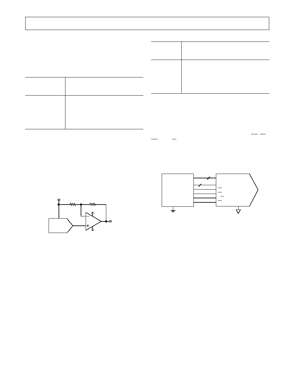
Bipolar Output Operation
The AD8600 can be configured for bipolar operation with the
addition of an op amp for each output as shown in Figure 20.
The output will now have a swing of
±
V
REF
, as detailed in Table
IV. This modification is only needed on those channels that re-
quire bipolar outputs. For channels which only require unipolar
output, no external amplifier is needed. The OP495 quad am-
plifier is chosen for the external amplifier because of its low
power, rail-to-rail output swing, and DC accuracy. Again, the
values calculated for the analog output are based upon an as-
sumed +2.5 V reference.
OUT
ø
1/4
OP495
+5V
5V
R1
10k
V
OUT
R1
10k
V
REF
V
REF
AD8600
Figure 20. Circuit for Bipolar Output Operation
Table IV. Bipolar Code Table
DAC
Binary Input
MSB LSB
Analog Output
1 1 1 1 1 1 1 1
+2 V
REF
(255/256) V
REF
= +2.49 V
1 0 0 0 0 0 0 1
+2 V
REF
(129/256) V
REF
= +0.02 V
1 0 0 0 0 0 0 0
+2 V
REF
(128/256) V
REF
= +0.00 V
0 1 1 1 1 1 1 1
+2 V
REF
(127/256) V
REF
= 0.02 V
0 0 0 0 0 0 0 1
+2 V
REF
(001/256) V
REF
= 2.48 V
0 0 0 0 0 0 0 0
+2 V
REF
(000/256) V
REF
= 2.50 V
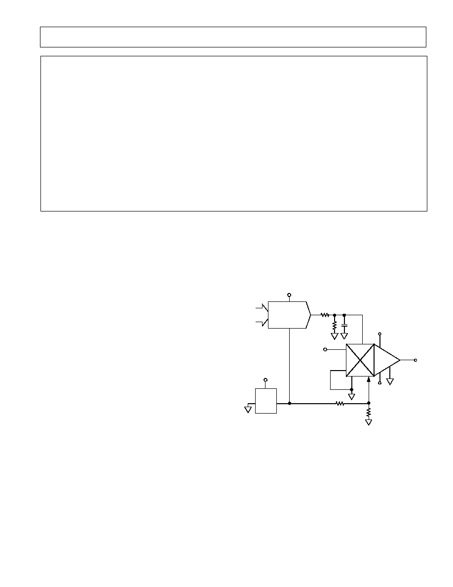
Interfacing to the 68HC11 Microcontroller
The 68HC11 is a popular microcontroller from Motorola,
which is easily interfaced to the AD8600. The connections be-
tween the two components are shown in Figure 21. Port C of
the 68HC11 is used as a bidirectional input/output data port to
write to and read from the AD8600. Port B is used for address-
ing and control information. The bottom 4 LSBs of Port B are
the address, and the top 4 MSBs are the control lines (LD, CS,
EN
, and R/W). The microcode for the 68 HC11 is shown in
Figure 22. The comments in the program explain the function
of each step. Three routines are included in this listing: read
from the AD8600, write to the AD8600, and a continuous loop
that generates a saw-tooth waveform. This loop is used in the
application below.
DB0DB7
A0A3
LD
EN
R/
W
CS
DGND1, DGND2
DACGND
8
4
DIGITAL GROUND
ANALOG GROUND
AD8600
MOTOROLA
68HC11
PC0PC7
PB0PB3
PB4
PB5
PB6
PB7
GND
Figure 21. Interfacing the 68HC11 to the AD8600

REV. 0
12
AD8600
* This program contains subroutines to read and write
* to the AD8600 from the 68HC11. Additionally, a ramp
* program has been included, to continuously ramp the
* output giving a triangle wave output.
*
* The following connections need to be made:
* 68HC11 AD8600
* GND DGND1,2
* PC0-PC7 DB0DB7 respectively, data port
* PB0-PB3 A0A3 respectively, address port
* PB4 LD
* PB5 EN
* PB6 R/W
* PB7 CS
*
portc equ $1003 define port addresses
portb equ $1004
ddrc equ $1007
*
org $C000
read lds #$CFFF subroutine to read from AD8600
*
ldaa #$00 initialize port c to 00000000
staa ddrc configures PC0-PC7 as inputs.
*
ldx #$00 points to DAC address in 68HC11 memory
ldaa 0,x put the address in the accumulator
adda #$70 add the control bits to the address
* R/W, LD, EN are high, CS is low.
staa portb output control and address on port b.
*
inx points to memory location to store the data
ldaa portc read data from DAC
staa 0,x Store this data in memory at address "x"
*
ldy #$1000
bset portb,y $f0 Set CS, LD, EN high
jmp $e000 Return to BUFFALO
*
*
write lds #$cfff routine to write to AD8600
ldaa #$ff initialize port c to 11111111
staa ddrc configures PC0-PC7 as outputs.
*
ldx #$00 points to DAC address in 68HC11 mem
ldaa 0,x puts the address in the accumulator
adda #$30 set CS, R/W low and LD, EN high
staa portb output to portb for control and address
*
inx points to memory location to store the data
ldaa 0,x load the data into the accumulator
staa portc write the data to the DAC
*
ldy #$1000
bclr portb,y $30 Set LD, EN low to latch data
bset portb,y $b0 Bring LD, EN, CS high, write is complete
*
jmp $e000 Return to BUFFALO
*
*
ramp lds #$cfff routine to generate a triangle wave
ldaa #$ff configure port c as outputs
AD8600
REV. 0
13
staa ddrc
*
ldx #$00 set x to point to the DAC address
ldaa 0,x load the address from 68HC11 mem
staa portb set the address on portb
* LD, CS, EN, R/W are all low for
* transparent DAC loading
ldab #$ff set accumulator b to 255
*
loop ldaa #$00 start the triangle wave at zero
staa portc write the data to the AD8600
*
load inca increase the data by one
staa portc send the new data to the AD8600
cba compare a to b
bne load we haven't reached 255 yet
jmp loop we have reached 255, so start over
Figure 22. 68HC11 Microcode to Interface to the AD8600.
Time Dependent Variable Gain Amplifier Using the AD600
The AD8600 is ideal for generating a control signal to set the
gain of the AD600, a wideband, low noise variable gain ampli-
fier. The AD600 (and similar parts such as the AD602 and
AD603) is often used in ultrasound applications, which require
the gain to vary with time. When a burst of ultrasound is ap-
plied, the reflections from near objects are much stronger than
from far objects. To accurately resolve the far objects, the gain
must be greater than for the near objects. Additionally, the sig-
nals take longer to reach the ultrasound sensor when reflected
from a distant object. Thus, the gain must increase as the time
increases.
The AD600 requires a dc voltage to adjust its gain over a
40 dB range. Since it is a dual, the two variable gain amplifiers
can be cascaded to achieve 80 dB of gain. The AD8600 is used
to generate a ramped output to control the gain of the AD600.
The slope of the ramp should correspond to the time delay
of the ultrasound signal. Since ultrasound applications often
require multiple channels, the AD8600 is ideal for this
application.
The circuit to achieve a time dependent variable gain amp is
shown in Figure 23. The AD600's gain is controlled by differ-
ential inputs, C1LO and C1HI, with a gain constant of
32 dB/V. Thus for 40 dB of gain, the differential control input
needs to be 1.25 V. In this application, the C1LO input is set at
the midscale voltage of 0.625 V, which is generated by a simple
voltage divider from the REF43. The AD8600's output is di-
vided in half, generating a 0 V to 1.25 V ramp, and then applied
to C1HI. This ramp sweeps the gain from 0 dB to 40 dB.
O
ø
+5V
5V
V
OUT
R1
10k
V
IN
V
REF
V
CC
, V
DD1
, V
DD2
AD8600
2
13
R2
10k
+5V
C1
100pF
0V 1.25V
4
6
REF43
+5V
2
+2.5V
DIGITAL
CONTROL
C1HI
16
2
3
A1HI
A1LO
4
GAT1
1
C1LO
V
POS
13
12
15
A1CM
14
A1OP
AD600
R3
30k
R4
10k
(FROM
ULTRASOUND
SENSOR)
0.625V
Figure 23. Ultrasound Amplifier with Digitally Controlled
Variable Gain
REV. 0
14
AD8600
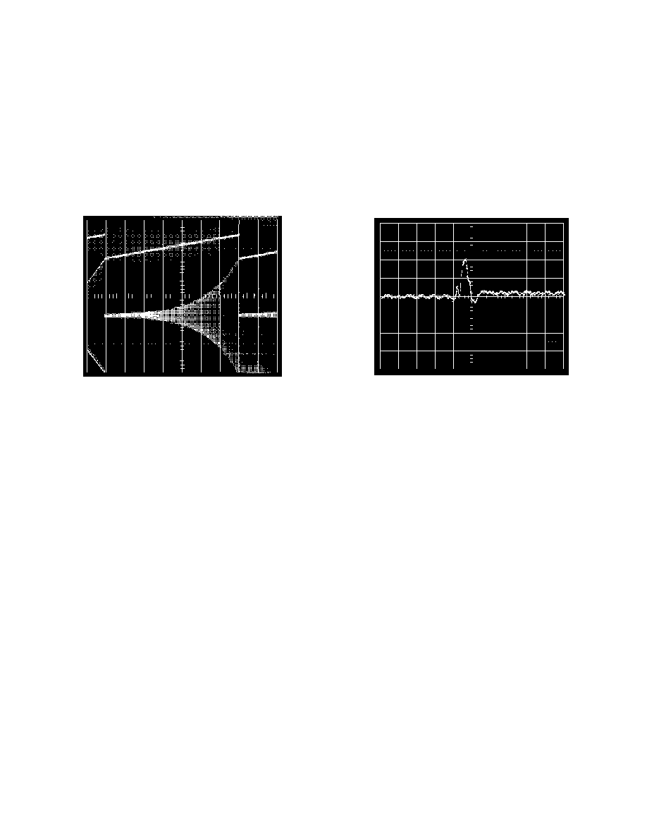
The functionality of this circuit is shown in the scope photo in
Figure 24 The top trace is the control ramp, which goes from
0 V to 1.25 V. The bottom trace is the output of the AD600.
The input is actually a 12 mV p-p, 10 kHz sine wave. Thus, the
bottom trace shows the envelop of this waveform to illustrate
the increase in gain as time progresses. This ramp was gener-
ated under control of the 68HC11 using the "ramp" subroutine
as mentioned above. The slope of the ramp can easily be
lengthened by adding some delay in the loop, or the slope can
be increased by stepping by 2 or more LSBs instead of the cur-
rent 1 LSB changes.
GAIN
CONTROL
1V/DIV
AD600
OUTPUT
0.2V/DIV
200µs/DIV
Figure 24. Time Dependent Gain of the AD600
Glitch Impulse
A specification of interest in many DAC applications is the
glitch impulse. This is the amount of energy contained in any
overshoot when a DAC changes at its major carry transition, in
other words, when the DAC switches from code 01111111 to
code 10000000. This point is the most demanding because all
of the R-2R ladder switches are changing state. The AD8600's
glitch impulse is shown in Figure 25. Calculating the value of
the glitch is accomplished by calculating the area of the pulse,
which for the AD8600 is: Glitch Impulse = (1/2)
×
(100 mV)
×
(200 ns) = 10 nV sec.
200ns/DIV
200ns/DIV
V
OUT
50mV/DIV
Figure 25. Glitch Impulse
AD8600
REV. 0
15
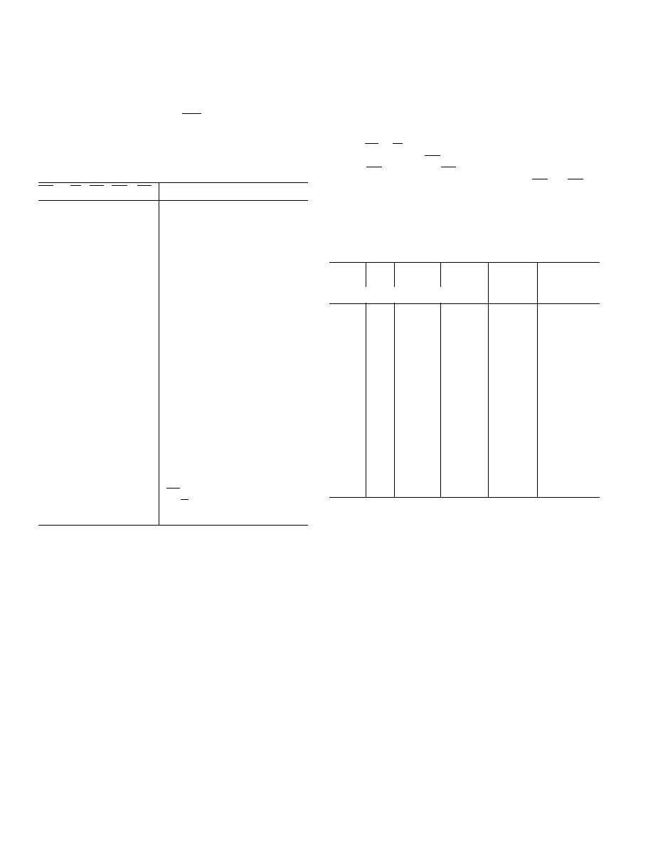
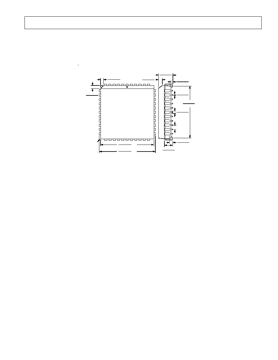
OUTLINE DIMENSIONS
Dimensions shown in inches and (mm).
44-Lead Plastic Lead Chip Carrier (PLCC) Package
(P-44A)
0.032 (0.81)
0.026 (0.66)
0.021 (0.53)
0.013 (0.33)
0.056 (1.42)
0.042 (1.07)
0.025 (0.63)
0.015 (0.38)
0.180 (4.57)
0.165 (4.19)
0.63 (16.00)
0.59 (14.99)
0.110 (2.79)
0.085 (2.16)
0.040 (1.01)
0.025 (0.64)
0.050
(1.27)
BSC
0.656 (16.66)
0.650 (16.51)
SQ
0.695 (17.65)
0.685 (17.40)
SQ
0.048 (1.21)
0.042 (1.07)
0.048 (1.21)
0.042 (1.07)
40
6
TOP VIEW
39
29
18
17
PIN 1
IDENTIFIER
7
28
0.020
(0.50)
R

REV. 0
16
AD8600
PRINTED IN U.S.A.
C1921187/94